Diffractive optical device and method for producing same

a diffractive optical element and optical device technology, applied in the field of diffractive optical elements, can solve the problems of difficult production of refractive index-modulated diffractive optical elements, difficult creation of effective diffraction-grating layers, photolithography and etching, etc., to achieve efficient production and low cost, the effect of making available practical diffractive optical elements

Inactive Publication Date: 2006-07-06
SUMITOMO ELECTRIC IND LTD
View PDF3 Cites 14 Cited by
  • Summary
  • Abstract
  • Description
  • Claims
  • Application Information

AI Technical Summary

Benefits of technology

[0013] An object of the present invention, in view of the situation as in the foregoing with prio...

Problems solved by technology

Although diffractive optical elements of the refractive-index-modulated type described above are manufacturable in principle, in practice producing refractive-index-modulated diffractive optical elements is problematic.
The reason is because with the amount of refractive-index variation obtained by irradiating for example quartz glass with an energy beam being at the very most 0.002 or so, creating an effective diffraction-grating layer is difficult....

Method used


Image

  • Diffractive optical device and method for producing same
  • Diffractive optical device and method for producing same
  • Diffractive optical device and method for producing same

Examples


embodiment 1

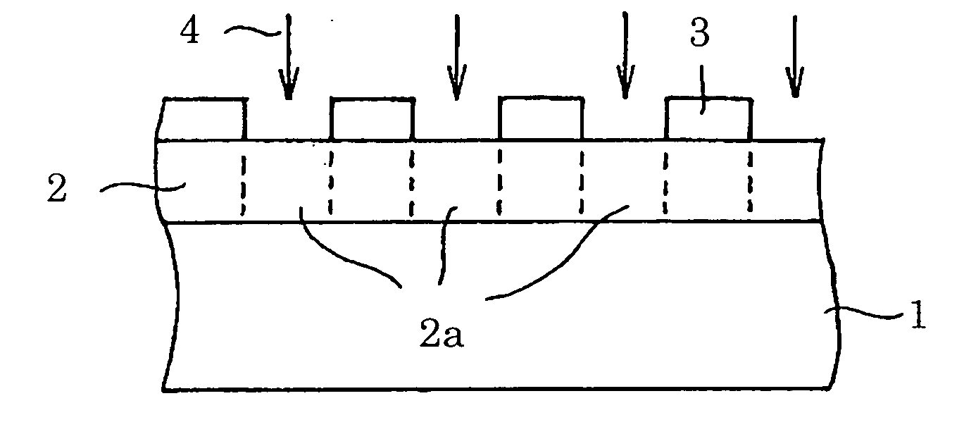
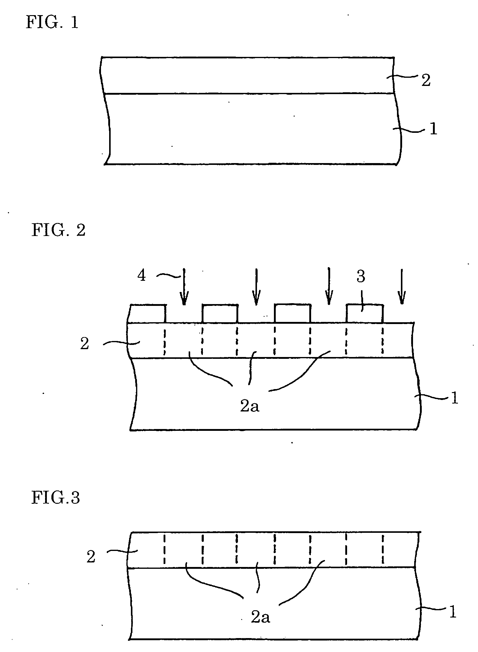
[0047]FIGS. 1 through 3 are schematic sectional views depicting a stage in the manufacture of a refractive-index-modulated diffractive optical element according to Embodiment 1 of the present invention. It should be understood that in the drawings for the present application, dimensional proportions such as length and thickness have been altered as appropriate in order to clarify and simplify the figures, and do not reflect the proportions in their actual relationships.

[0048] Onto an SiO2 substrate 1, as represented in FIG. 1, having a 1.44 refractive index and having a 5 mm×5 mm principal face, a DLC film 2 was deposited by plasma CVD to a thickness of 2 μm. It will be appreciated the thickness of the DLC film in the refractive-index-modulated diffractive optical element is not particularly limited, and can be set to a thickness of choice. Nevertheless, it would be disadvantageous if the DLC film were too thick, in that the light-absorbing efficacy through the film would grow too ...

embodiment 2

[0056]FIG. 6 shows, in a schematic plan view, a two-dimensional diffraction-grating pattern in a diffractive optical element according to Embodiment 2. The diffractive optical element of Embodiment 2 can be fabricated by a manufacturing process likewise as was the case with Embodiment 1. In particular, the black regions in FIG. 6 represent where within the DLC film the refractive index was raised by irradiating the regions with the He ion beam, while the white areas represent regions that were not irradiated with the He ion beam. The black pattern was formed by combining 4 μm×4 μm microcells, and therein had a periodicity of 132 μm. This means that the minimum linewidth in the diffraction-grating pattern illustrated in FIG. 6 is 4 μm.

[0057]FIG. 7 depicts, in a schematic sectional view, power-splitting action in a case in which the refractive-index-modulated diffractive optical element produced in Embodiment 2 is employed as an optical coupler (power splitting device). In particular...

embodiment 3

[0060] In Embodiment 3, a diffractive optical element having polarization-division multiplexing / demultiplexing functionality was fabricated. With the diffractive optical element of Embodiment 3 as well, a DLC diffraction-grating layer having a “line & space” pattern was formed by a manufacturing process likewise as was the case with Embodiment 1. In Embodiment 3, however, high refractive-index regions of 0.4 μm width and 5 mm length were arrayed in iterations at a pitch of 0.4 μm.

[0061]FIG. 9 depicts in a schematic sectional view polarization-demultiplexing action in case in which the refractive-index-modulated diffractive optical element produced in Embodiment 3 was employed as a polarization-division multiplexer / demultiplexer. In particular, if a TEM wave including a TE component and a TM component is made incident on the diffractive optical element of Embodiment 3, the TE wave and the TM wave will, depending on the difference in polarization between them, be diffracted at diffra...


PUM


Abstract

Practical diffractive optical elements are made available efficiently and at low-cost. A refractive-index-modulated diffractive optical element includes a transparent DLC (diamond-like carbon) film (2) formed on a transparent substrate (1), with the DLC film (2) containing a diffraction grating having local regions (2a) of a relatively high refractive index and local regions (2) of a relatively low refractive index. The DLC film (2) can readily be deposited by plasma CVD onto the substrate (1), and the high refractive-index regions (2a) within the DLC film can readily be formed by irradiating it with an energy beam (4) such as an ion beam.

Description

TECHNICAL FIELD [0001] The present invention relates to diffractive optical elements and methods of their formation, and more particularly, to diffractive optical elements having wavelength-division multiplexing / demultiplexing, power-splitting / combining, polarization-division multiplexing / demultiplexing, wave-plate, or optical-isolator functionality, and to methods of forming such diffractive optical elements. BACKGROUND ART [0002] As is widely known, diffractive optical elements that produce diffraction of light can be employed in a variety of applications. For example, wavelength-division multiplexers, optical couplers, optical isolators, and like devices used in optical communications fields can be manufactured employing diffractive optical elements. [0003] Diffractive optical elements generally are manufactured by forming a diffraction-grating layer on a transparent substrate. Diffractive optical elements are grossly divided, based on structural differences in the diffraction-gr...

Claims


Application Information

Patent Timeline
IPC IPC(8): G02B5/18G02B27/44G02B26/08
CPCG02B5/1857G02B26/0808G02B5/1866G02B5/18G02B5/30
Inventor USHIRO, TOSHIHIKOOKUBO, SOICHIROMATSUURA, TAKASHI
Owner SUMITOMO ELECTRIC IND LTD
Why Eureka
Try Eureka