
Surge suppressor with increased surge current capability

a surge suppressor and surge current technology, applied in the field of surge suppressors, can solve the problems of reducing the current handling capability, and affecting the performance of passive intermodulation, so as to increase the surge current capability and improve the effect of passive intermodulation performan

Inactive Publication Date: 2006-07-06
HUBERSUHNER AG
View PDF5 Cites 31 Cited by
  • Summary
  • Abstract
  • Description
  • Claims
  • Application Information

AI Technical Summary

Benefits of technology

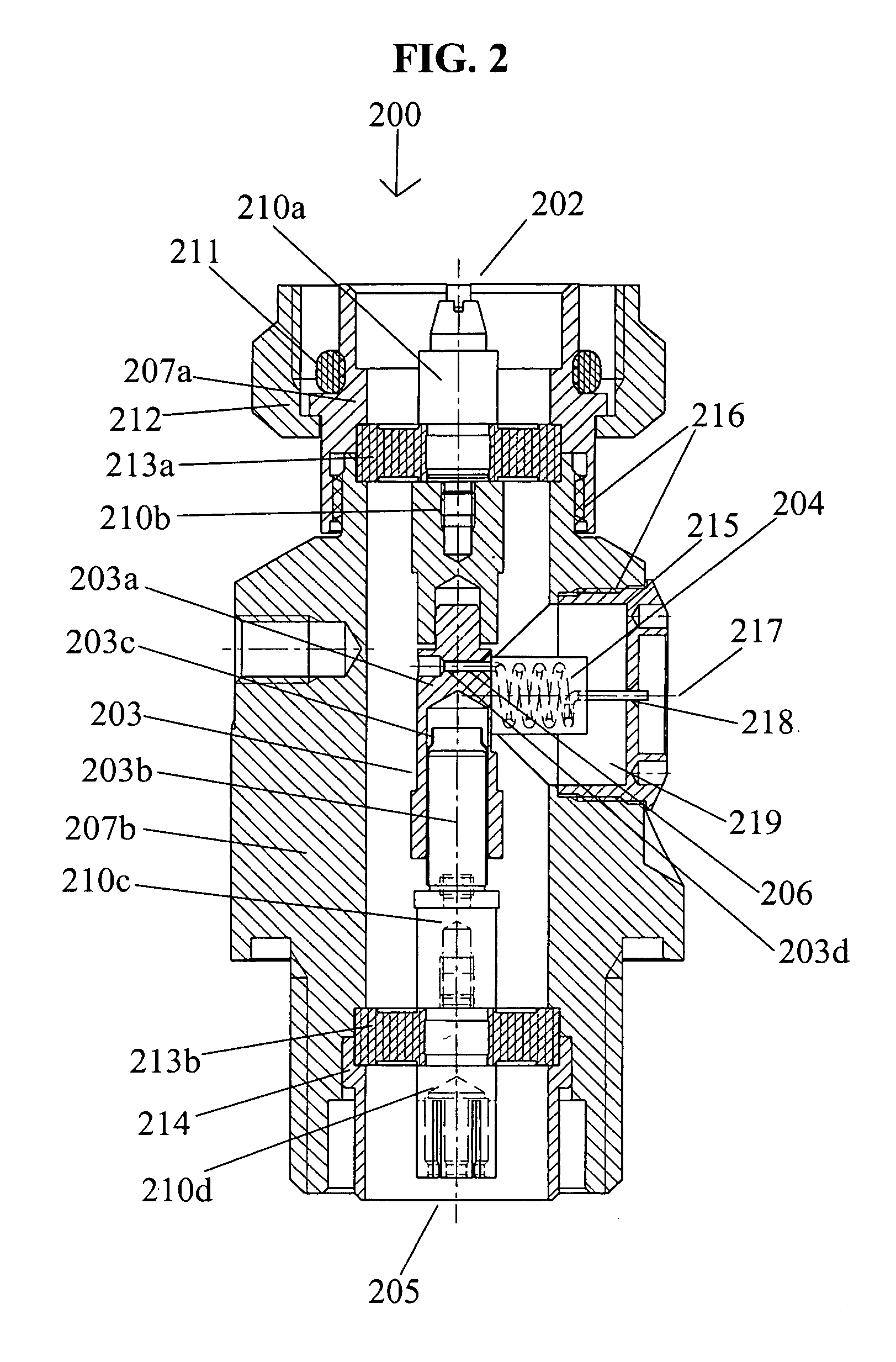
"The present invention provides a surge suppressor that can handle high current pulses without deviation in performance. The inductor is fixed in a mechanically stable medium, and the ends of the inductor wire are fixed to the inner and outer conductors by soldering, which enhances the passive intermodulation performance of the surge suppressor. The inductor includes a wire encapsulated in an encapsulating material, which is in the form of a cylinder larger than the coil. The inner conductor includes a first segment, a second segment, and a third segment which are releasably connected along a longitudinal axis, and the second segment carries the inductor and the capacitor. The wire of the inductor has a resistance of less than 3 mΩ, and the encapsulating material has a relative permittivity between 3.0 and 3.5 and a hardness between 65 and 70 Shore D to ensure sufficient mechanical strength to withstand the deformation of the inductor wire that results from high current pulses. The inductor has a longitudinal axis that extends generally perpendicular to a longitudinal axis of the inner conductor, and the second segment can be rotated 180° about a longitudinal axis of the inductor without changing an axial position of the inductor with respect to the outer conductor."

Problems solved by technology

In particular, electronic devices that receive RF signals from antennas or transmission lines (which are typically coaxial cable) are particularly susceptible to electrical surges, because a) transmission lines often carry electrical power signals as well as information signals; and b) transmission lines are typically suspended above the ground, attached to poles or other structures for long distances where they are susceptible to lightning strikes and power interruptions due to broken lines.
Lightning strikes are known to reach potentials of 5 to 20 million volts with currents of thousands of amps and thus pose a significant threat to downstream electronic equipment.
These types of connections, however, cause the passive L-C components to act non-linearly, thus significantly reducing the current handling capability and degrading the passive intermodulation performance of the surge suppressor.
Additionally, the solderless connections and physical configuration of the inductor make it susceptible to deformation by electromagnetic forces created by the high pulse currents associated with a lightning surge.
Deformation of the inductor will change the frequency response characteristics and eventually lead to failure of the surge suppressor to properly conduct the electrical surge to ground, thereby damaging the device and possibly downstream electronic components.
However, the design and tuning processes for such spiral inductors are complicated and time consuming, requiring multiple design and manufacturing iterations and testing to achieve the desired input impedance for low VSWR and insertion loss.

Method used


Image

  • Surge suppressor with increased surge current capability
  • Surge suppressor with increased surge current capability
  • Surge suppressor with increased surge current capability

Examples


Embodiment Construction

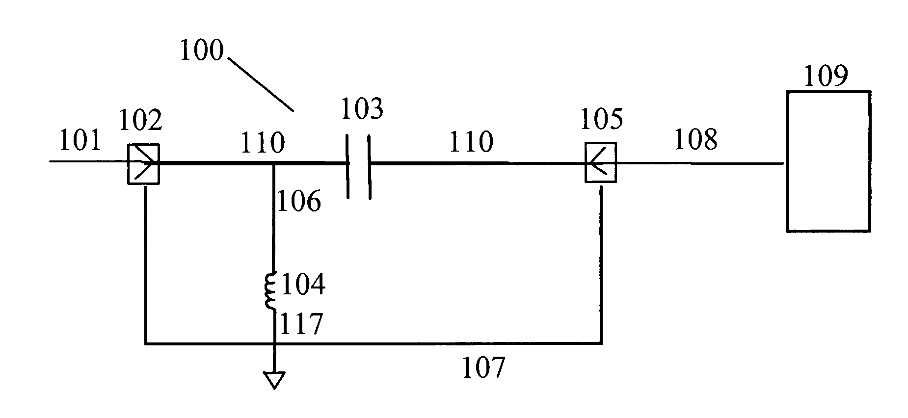
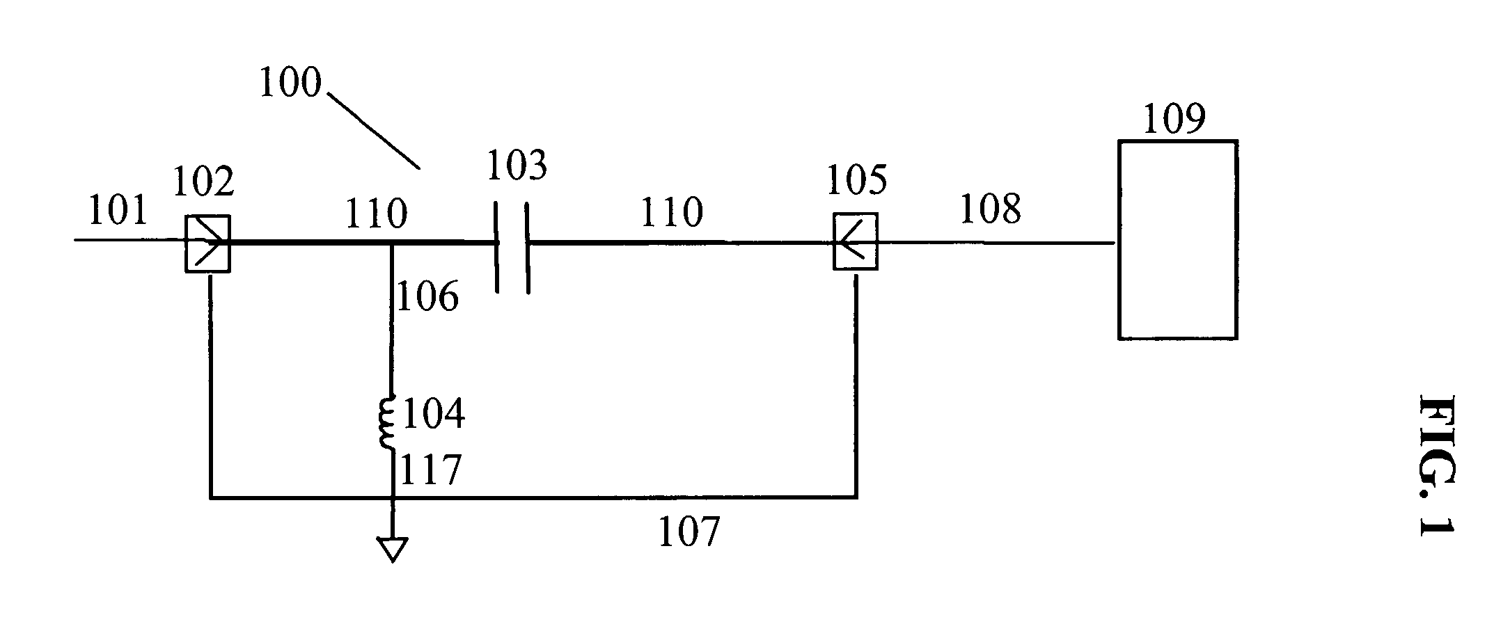
[0022]FIG. 1 is a schematic drawing of a surge suppressor 100 in accordance with one embodiment of the present invention. Surge suppressor 100 includes capacitive element 103, inductor 104, inner conductor 110, outer conductor 107, and first 102 and second 105 connectors. First 102 and second 105 connectors couple RF signals into and out of surge suppressor 100. In the embodiment shown in FIG. 1, first connector 102 is on the unprotected side of surge suppressor 100 and second connector 105 is on the protected side. Capacitive element 103 is serially connected between first 102 and second 105 connectors. The value of capacitive element 103 is selected to have a low impedance to RF signals in the desired operating bandwidth thereby allowing those frequencies to pass through surge suppressor 100 relatively unimpeded. The value of capacitive element 103 is further selected to have a high impedance to electrical surges caused by lightning, for example, which typically occur at frequenci...


PUM


Abstract

A surge suppressor configured to receive signals from a coaxial line having a signal carrying inner conductor and a grounded outer conductor. The surge suppressor includes an inner conductor exhibiting capacitance and configured to connect to the coaxial line inner conductor, an outer conductor configured to connect to the coaxial line outer conductor and to ground, and an inductor formed of a wire encapsulated in an encapsulating material electrically coupling the inner conductor and the outer conductor. RF signals in the surge suppressor's operating bandwidth pass through the surge suppressor relatively unimpeded while electrical surges will be diverted through the inductor to the outer conductor, and therefore to ground, and possible residual pulses will be blocked from passing through the surge suppressor by the capacitance.

Description

FIELD OF THE INVENTION [0001] The present invention generally relates to the field of surge suppressors for the protection of sensitive electronic equipment from an electrical surge. More specifically, the present invention relates to L-C filter type surge suppressors serially connected between transmission lines and protected electronic equipment. BACKGROUND OF THE INVENTION [0002] Surge suppression devices are well known in the art for protecting sensitive electronic devices from electrical surges due to power line fluctuations and lightning, for example. In particular, electronic devices that receive RF signals from antennas or transmission lines (which are typically coaxial cable) are particularly susceptible to electrical surges, because a) transmission lines often carry electrical power signals as well as information signals; and b) transmission lines are typically suspended above the ground, attached to poles or other structures for long distances where they are susceptible t...

Claims


Application Information

Patent Timeline
Patent Type & Authority Applications(United States)
IPC IPC(8): H02H9/00
CPCH01Q1/50H01T4/08
Inventor MUELLER, MARCO
Owner HUBERSUHNER AG
Learn More