
Unidirectional lighting device for illuminating objects and/or for marking lanes, preferably in the airport area

a technology of unidirectional lighting and objects, which is applied in the direction of lighting and heating apparatus, landing aids, lighting support devices, etc., can solve the problems of only partly possible, difficult to achieve corrosion resistance, and inability to change the light source of this known lighting device, so as to reduce the risk of breakage, the angle is accurate, and the effect of stable non-metallic external housing

Active Publication Date: 2006-07-06
ADB SAFEGATE BVBA
View PDF9 Cites 13 Cited by
  • Summary
  • Abstract
  • Description
  • Claims
  • Application Information

AI Technical Summary

Benefits of technology

[0006] According to the invention, the problem is solved by a lighting device of the type in question, said lighting device having the features described herein. As a result of the combination of the partly metallic optical components in a separate optics module which can be installed in the main body of the lighting device, and as a result of the construction of large parts of the external housing of the main body from non-metallic materials, a lower overall weight of the claimed lighting device is achieved, thereby making it easier to replace in the field. As a result of using non-metallic materials for the external housing, in particular a higher corrosion-resistance is achieved for a lighting device in accordance with the invention. Furthermore, the embodiment of the overall lighting device can be smaller, thereby reducing the wind sensitivity and therefore the danger of breakage. Consequently, it is possible to fasten a lighting device according to the invention onto higher masts than in the prior art. The non-metallic and therefore non-conducting construction of the external housing allows the insulated fastening of a drive amplifier of the lighting device, thereby allowing the reliable transmission of triggering signals even over cable lengths up to 250 m. The plastic construction of the external housing provides for greater flexibility in layout and production and for better frictional behavior. Due to the limited heat conductivity and electrical conductivity of non-metallic materials, there are fewer problems taking hold of and handling an external housing of corresponding construction.
[0012] The non-metallic external housing of the main body is preferably designed as a plastic part, in particular an injection molded part. In this way, stable non-metallic external housings can be provided at low manufacturing cost for lighting devices in accordance with the invention.

Problems solved by technology

A change of the light source in this known lighting device is possible without tools, but can only be carried out at the erection location in the field via a door which is arranged on the rear panel of the external housing.
The main body of the lighting device consists of a cast aluminum external housing and noble metal parts, and corrosion resistance is therefore difficult to achieve and only partly possible.
Furthermore, the embodiment of the overall lighting device can be smaller, thereby reducing the wind sensitivity and therefore the danger of breakage.

Method used


Image

  • Unidirectional lighting device for illuminating objects and/or for marking lanes, preferably in the airport area
  • Unidirectional lighting device for illuminating objects and/or for marking lanes, preferably in the airport area
  • Unidirectional lighting device for illuminating objects and/or for marking lanes, preferably in the airport area

Examples


Embodiment Construction

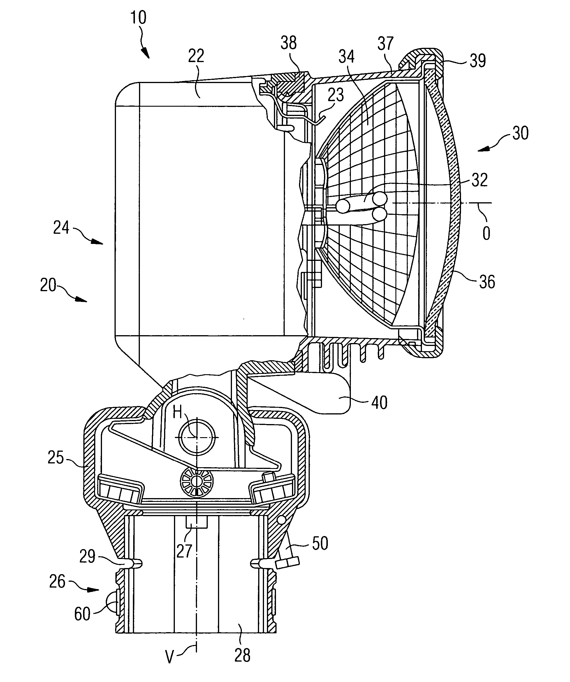
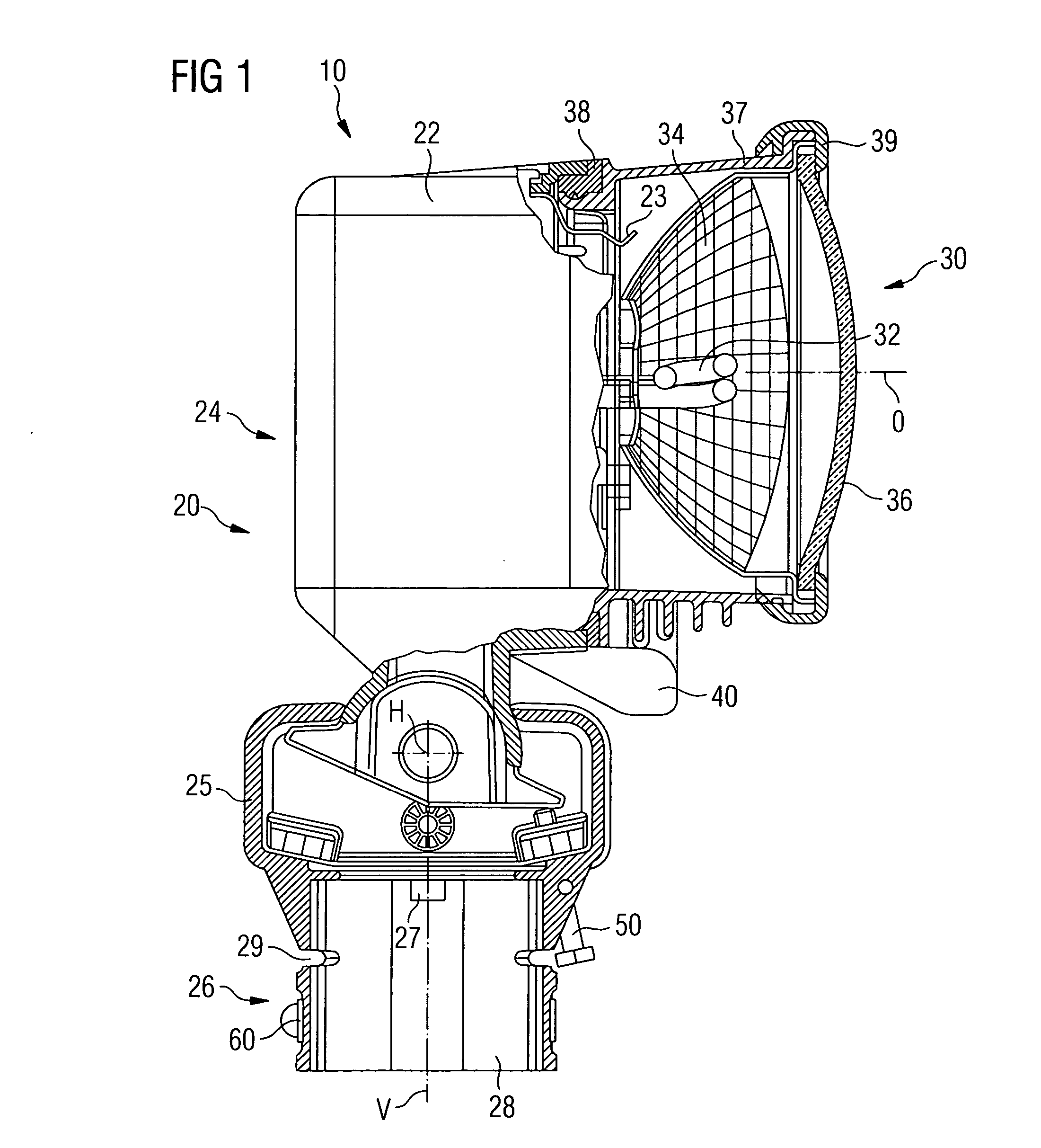
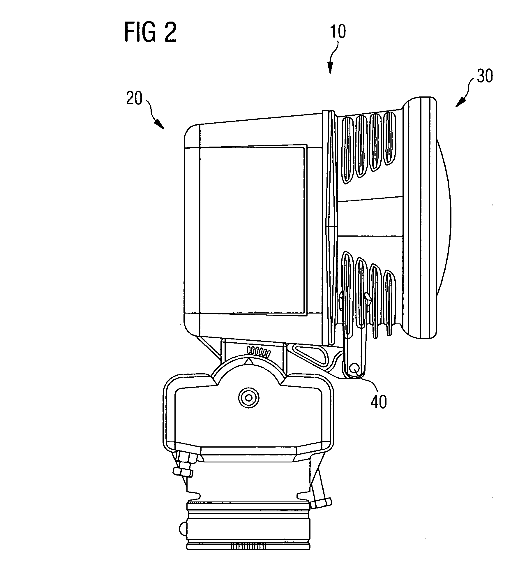
[0018] As shown in FIG. 1, a lighting device 10 according to the invention has a main body 20 for erecting and fastening the lighting device 10 and an optics module 30 for generating a light beam along an optical axis O. The main body 20 is enveloped by a non-metallic external housing 22 and essentially comprises an upper part 24, an intermediate part 25 and a lower part 26. The optics module 30 is laterally attached to the upper part 24 of the main body 20, which upper part also contains electrical components for controlling and operating the optics module 30. The upper part 24 is supported on the intermediate part 25 by means of a hinge bolt which is aligned longitudinally along a horizontal axis of rotation H, and is therefore tiltably positioned about the axis of rotation H which extends perpendicularly to the page plane. The intermediate part 25 of the main body 20 is rotatably positioned on the lower part 26 about a vertical axis V. For this purpose, the intermediate part 25 i...


PUM


Abstract

The invention relates to a unidirectional lighting device for illuminating objects and / or for marking lanes, preferably in the airport area. Said device comprises a base having an external housing for placing and fastening the lighting device and optical components which comprise at least one light source, one reflector and one front glass and which produce a light beam along an optical axis. The external housing does not consist of metal and the optical components are disposed in an optical module to be added on to the base, thereby providing a lighting device which is easy to maintain.

Description

CROSS REFERENCE TO RELATED APPLICATIONS [0001] This application is the US National Stage of International Application No. PCT / EP2004 / 006623, filed Jun. 18, 2004 and claims the benefit thereof. The International Application claims the benefits of German application No. 10329496.1, filed Jun. 30, 2003, both applications are incorporated by reference herein in their entirety FIELD OF INVENTION [0002] The invention relates to a unidirectional lighting device for illuminating objects and / or for marking lanes, preferably in the airport area. SUMMARY OF THE INVENTION [0003] The publication entitled “Approach, Threshold Runway End High Intensity Elevated Light” published by ADB, a Siemens company, Apr. 11, 1997, order number E10001-T95-A61-V1-7600 discloses a unidirectional lighting device for marking the approach and threshold area as well as the takeoff and landing path limits of airports. The lighting device comprises a main body having an external housing which can be erected and fasten...

Claims


Application Information

Patent Timeline
IPC IPC(8): F21V21/30B64F1/20F21V17/10F21V19/04
CPCB64F1/20F21V17/107F21V19/04F21V21/30
Inventor LAENEN, GUYVANDEVOORDE, JEAN-CLAUDEWILLEMS, LOUIS
Owner ADB SAFEGATE BVBA
Learn More