Method and apparatus for accessing for storage system

a storage system and access method technology, applied in the field of computer system technique, can solve the problems of system reset, inability to control access, lack of flexibility,

Inactive Publication Date: 2006-07-06
HITACHI LTD
View PDF7 Cites 6 Cited by
  • Summary
  • Abstract
  • Description
  • Claims
  • Application Information

AI Technical Summary

Benefits of technology

[0009] For preventing data destruction caused by double writing to the disk apparatus, exclusive control on disk access is necessary. If a fault has occurred in the system itself, however, the disk access cannot be controlled using the cluster software alone and consequently the system itself must be reset. In a system in which resetting is conducted, dedicated hardware having a reset mechanism is indispensable, resulting in a problem of the lack of flexibility. Furthermore, since the reset mechanism is needed, a cost is required also when adding a new computer to a system having a cluster configuration. Furthermore, for investigating a fault cause of a faulty system, processing of preserving the memory dump in the disk apparatus before resetting becomes necessary.
[0010] In view of the problem, an object of the present invention is to provide means for exercising exclusive control on access to a storage apparatus in a cluster system conducting system changeover.
[0011] In order to solve the problems, the present invention a storage access control method in a cluster system including a computer of execution system for conducting predetermined processing, a computer of stand-by system responsive to occurrence of a fault in the computer of execution system to take over processing conducted by the computer of execution system, a storage apparatus accessed by the computer of execution system and the computer of stand-by system in

Problems solved by technology

If a fault has occurred in the system itself, however, the disk access cannot be controlled using the cluster software alone and consequently the system itself must be reset.
In a system in which resetting is conducted, dedicated hardware

Method used


Image

  • Method and apparatus for accessing for storage system
  • Method and apparatus for accessing for storage system
  • Method and apparatus for accessing for storage system

Examples


first embodiment

1. First Embodiment

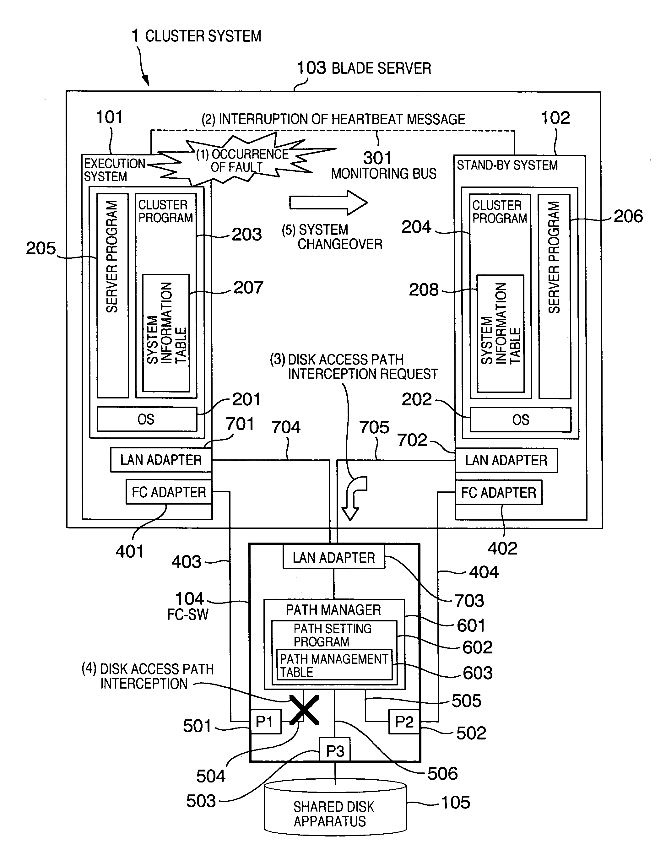
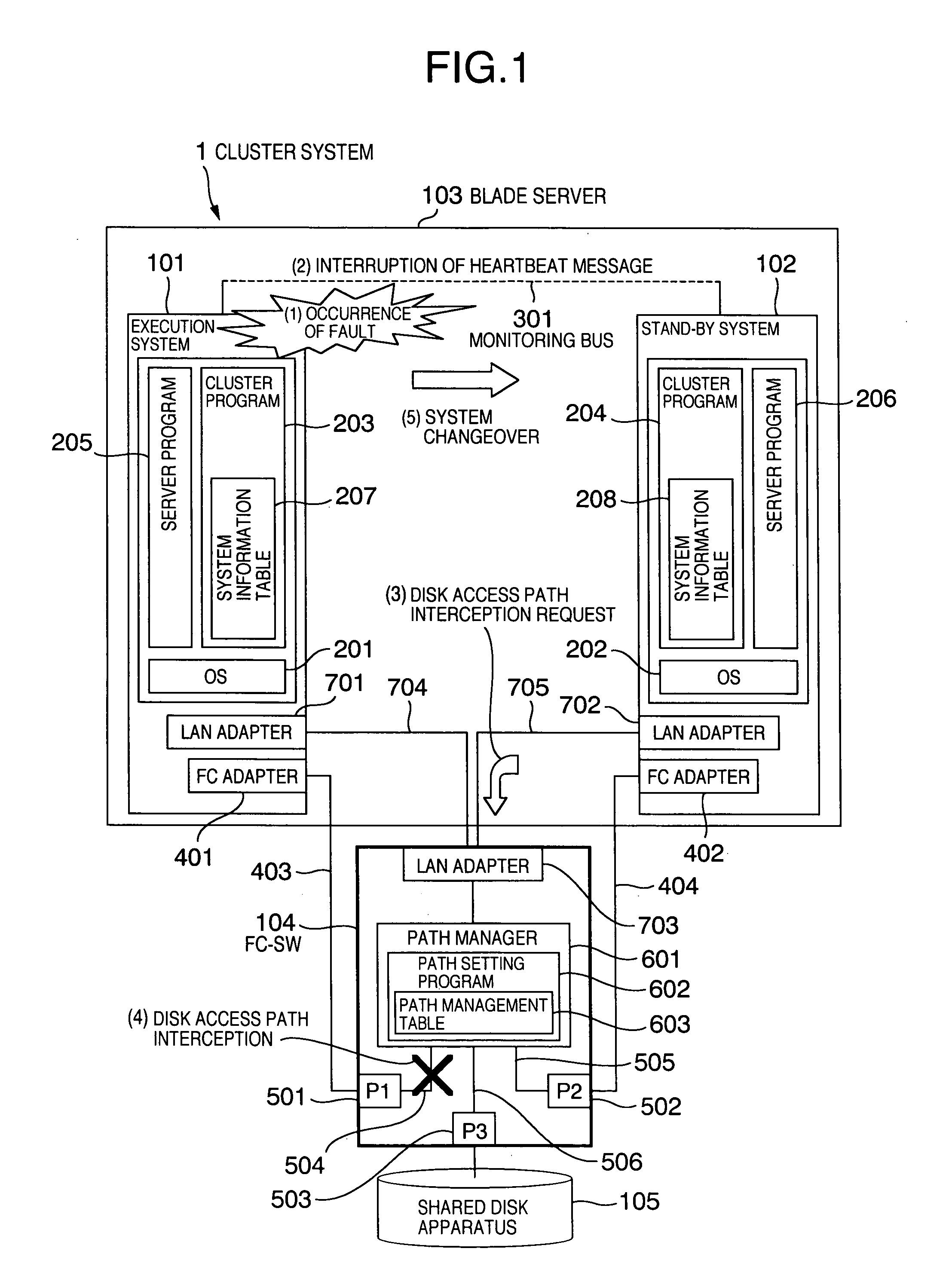
[0026]FIG. 1 is a diagram showing a functional configuration of a cluster system. A cluster system 1 includes a blade server 103, an FC-SW (Fiber Channel-Switch) 104, and a shared disk apparatus 105.

[0027] The blade server 103 includes an execution system 101 and a stand-by system 102. Here, the system corresponds to, for example, a blade (server board) incorporated in the blade server 103, and it corresponds to one computer capable of conducting predetermined business processing. Hereafter, the system is referred to as computer as well. The execution system 101 is a computer that is currently executing business processing (processing). The stand-by system 102 is a computer that does not currently conduct business processing and that takes over the business processing when a fault has occurred in the execution system 101. In other words, the stand-by system 102 is a computer that is waiting for the system changeover. OSs 201 and 202, cluster programs 203 and 204,...

second embodiment

2. Second Embodiment

[0046] A second embodiment will now be described. Description that overlaps that of the first embodiment will be omitted.

[0047]FIG. 5 is a diagram showing a functional configuration of a cluster system. Especially, FIG. 5 is a diagram showing the case where the management processor controls the FC-SW. In FIG. 1, the cluster program 204 controls the FC-SW 104. In a cluster system 1 in which a management processor 710 is incorporated in the blade server 103 as shown in FIG. 5, however, the management processor 710 controls the FC-SW 104. In FIG. 5, the LAN adapters 701 and 702 are connected to the management processor 710. The cluster program 204 issues a disconnection request for a disk access path from the faulty system 101 to the management processor 710. As a result, an FC-SW control program 711 operating in the management processor 710 issues a path disconnection request to the FC-SW 104, and the path setting program 602 in the FC-SW 104 disconnects the path ...

third embodiment

3. Third Embodiment

[0052] A third embodiment will now be described. Description that overlaps that of the above-described embodiments will be omitted.

[0053] In the case where a plurality of computers share the disk apparatus, it is possible in the FC-SW to define a port group in order to prevent illegal writing to the disk apparatus which is being used by another computer. Computers connected to ports belonging to different groups cannot recognize each other. This technique is called zoning. Illegal disk access can be prevented by using the zoning and separating the port of the faulty system to a different zone in response to occurrence of a system fault.

[0054]FIG. 8 is a diagram showing a configuration of a zone management table. The zone management table is a table provided for conducting exclusive access control between computers (the execution system (faulty system) 101 and the stand-by system 102) connected to ports and the shared disk apparatus 105 by changing ports belongin...


PUM


Abstract

Exclusive control is exercised on access to a storage apparatus in a cluster system conducting system changeover. If a system fault has occurred in an execution system, a heartbeat message to a stand-by system is interrupted. A cluster program in the stand-by system detects a fault in the execution system. The cluster program transmits a request to a path setting program in an FC-SW to change over a disk access path from the execution system. Upon receiving the request, the path setting program rewrites a path management table, intercepts the disk access path from the execution system, and transmits a result of the processing to the cluster program. Upon receiving the result, the cluster program starts a server program. The server program starts business processing from a check point at the time when the business processing is stopped due to occurrence of the fault in the execution system.

Description

INCORPORATION BY REFERENCE [0001] The present application claims priority from Japanese application JP2004-381999 filed on Dec. 28, 2004, the content of which is hereby incorporated by reference into this application. BACKGROUND OF THE INVENTION [0002] The present invention relates to a computer system technique having a fault tolerance by including an execution system and a stand-by system. Furthermore, the present invention relates to an access control technique in communication in a computer. [0003] If a fault has occurred in a certain system in a cluster system including a plurality of systems and a shared disk apparatus, processing can be continued by conducting changeover (hot swapping) to another system in the stand-by state. In such a system changeover system, there is a fear that data will be destroyed when writing to the shared disk apparatus is conducted simultaneously from a plurality of systems. Therefore, exclusive control becomes necessary in access to the shared disk...

Claims


Application Information

Patent Timeline
IPC IPC(8): H04L12/50
CPCH04L41/06H04L67/1097
Inventor TSURUMI, RYOSUKEBABA, TSUNEHIKO
Owner HITACHI LTD
Why Eureka
Try Eureka