
Method and device for frame detection and synchronizer

Inactive Publication Date: 2006-07-06
IHP GMBH INNOVATIONS FOR HIGH PERFORMANCE MICROELECTRONICS LEIBNIZ INST FUR INNOVATIVE
View PDF3 Cites 54 Cited by
  • Summary
  • Abstract
  • Description
  • Claims
  • Application Information

AI Technical Summary

Benefits of technology

[0013] It is an object of the invention to provide a simple and reliable method and device for detection of the reception of a data frame in an input signal.
[0014] It is a further object of the invention to provide a synchronizing method and a synchronizer with a simple and reliable frame detector.
[0024] A maximum of the differentiator signal can be detected with precise timing in a simple and reliable manner with an appropriate peak detection method.
[0030] In a further preferred embodiment, the step of detecting an absolute maximum of the differentiator signal within a second predetermined number of sampling periods comprises an instantaneous peak detection step and a step of detecting a falling slope in the differentiator signal. Preferably, these two steps are performed in parallel. Instantaneous peak detection refers to the detection of a relative peak in the differentiator signal. The detection of a relative peak at the same time a falling slope occurs is an indication of the occurrence of an absolute maximum in the signal within the second predetermined number of sampling periods. In this embodiment, the detection of an absolute maximum in the differentiator signal is implemented with a simple and reliable method.

Problems solved by technology

The fact that the different sub-carriers overlap their spectra makes one of the main operations at the receiver especially difficult: synchronization.
Frame detection in a receiver is an especially difficult task because there is no time raster that governs the transmission of the frames.
A major problem in the use of OFDM is therefore the determination of the time instant, at which the receiver starts sampling a new frame.
A mismatch in the determination of this parameter would introduce a phase error causing intercarrier interference (ICI).
However, in the solution proposed by Chiu et al. the frame detection does not work if a fading channel is affecting the signal.
This implies a rather large silicon area necessary for implementation of their solution and a high power consumption.

Method used


Image

  • Method and device for frame detection and synchronizer
  • Method and device for frame detection and synchronizer
  • Method and device for frame detection and synchronizer

Examples


Embodiment Construction

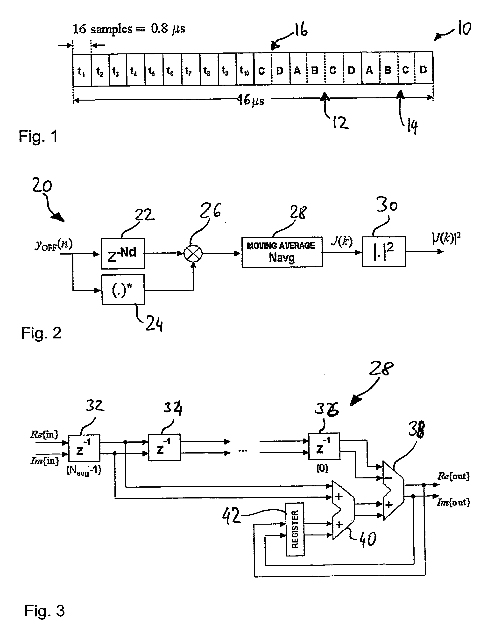
[0084]FIG. 1 shows the structure of a preamble 10 of a frame used in the IEEE 802.11a standard. It is composed of ten short preamble symbols referred to as t1, . . . , t10, each having a length of 0.8 μs. A short preamble symbol is sampled 16 times. Furthermore, there are two long preamble symbols 12 and 14 (ABCD-ABCD) with a double cyclic prefix 16 (CD), thus resulting in the structure CD-ABCD-ABCD of the second section of the preamble. The full preamble as shown has a duration of 16 μs. 8 μs is the duration of the short ten preamble symbols, and 8 μs is the duration of the long preamble symbols with the cyclic prefix.

[0085] In the following, an embodiment of a frame detector is described in detail. The description also gives a clear picture of an embodiment of a method for frame detection that is implemented in the frame detector.

[0086] During synchronization the reception of a frame is to be detected. This detection is based on the particular periodic structure of the preamble ...


PUM


Abstract

The IEEE 802.11a standard uses OFDM, where the transmission is divided into several orthogonal sub-carriers. Here, an algorithm is used for the frame detection; a simplified differentiator obtains an absolute maximum in the differentiated signal at that point where the first plateau in JF(k) starts; a peak detector obtains the position of the absolute maximum in the differentiated signal, divides the problem into relative peak detection and falling edge detection; a simplified XNOR-based crosscorrelator is used, where the simplifications are based on the knowledge of the reference; a particular solution is provided for the CORDIC algorithm in the vectoring mode for arctangent calculation; hardware structuring is presented for the whole synchronizer so as to obtain a simple control mechanism and the separation of this structure into different clock domains, each one being activated only to perform its operation and deactivated afterwards.

Description

[0001] The present invention concerns a method for the detection of the reception of a data frame in an input signal, said data frame comprising periodically repeated symbols at the beginning. It further concerns a frame detector, a synchronizing method, and a synchronizer device. BACKGROUND OF THE INVENTION [0002] The IEEE 802.11a standard makes use of the Orthogonal Frequency Division Multiplex (OFDM) transmission scheme. The main feature of the OFDM scheme is that the information stream is not transmitted into a single carrier, but is divided into several sub-carriers, each transmitting at a much lower rate. [0003] Furthermore, all these sub-carriers are orthogonal, i.e., they overlap their spectra, but do not cause mutual interference. [0004] The fact that the different sub-carriers overlap their spectra makes one of the main operations at the receiver especially difficult: synchronization. In a receiver, the synchronizer is the block responsible for detecting the incoming frame...

Claims


Application Information

Patent Timeline
IPC IPC(8): H04L27/06H04L27/26
CPCH04L27/2656H04L27/2675
Inventor TROYA, ALFONSOMAHARATNA, KOUSHIKKRSTIC, MILOSGRASS, ECHKHARD
Owner IHP GMBH INNOVATIONS FOR HIGH PERFORMANCE MICROELECTRONICS LEIBNIZ INST FUR INNOVATIVE
Learn More