Slicing machine, method of use and components thereof

a technology of slicing machine and slicer, which is applied in the field of slicing machine, can solve the problems of limited height of the food slice stack, and achieve the effect of improving the quality of the sliced product and being more efficient to opera

Inactive Publication Date: 2006-07-13
BERKEL & CONTRACTORS +1
View PDF37 Cites 35 Cited by
  • Summary
  • Abstract
  • Description
  • Claims
  • Application Information

AI Technical Summary

Benefits of technology

[0015] The present invention is generally directed to an ergonomically designed food slicing machine which provides improved quality of sliced product and is more efficient to operate in both manual and automatic mode.
[0016] In one embodiment of the invention, the slicing machine includes a rotatable blade for slicing bulk food product, a motor operably connected to the rotating blade, and a base portion located below the rotatable blade which defines a portion of the periphery of a food slice receiving area for accepting the sliced food product as it falls from the blade after slicing. This design provides a substantially open area below the blade to receive the sliced food product so that slices generated during automatic operation may reach a substantial stack height. Prior food slicing machines typically included a tray area of substantial thickness below the slicing blade which limited the attainable height of the food slice stack. This tray area of the base of prior slicing machines typically housed a portion of the motor for rotating the blade or other internal workings of the machine.
[0017] In another embodiment of the invention, a visible slice thickness indicia is located adjacent to the blade so that it can be viewed by the operator at the same time as the slicing blade. The visible indicia correlated to the distance between one adjustable gauge plate and the slicing blade which distance determines slice thickness. The visible indicia includes a support surface which is connected to a portion of the slicing machine adjacent to the rotatable blade and adjustable gauge plate and a visible indicia located on the support which correlates with the distance between an adjustable gauge plate and the blade so that the operator may view the visible indicia simultaneously with viewing the blade during food product slicing. This feature of one embodiment of the invention allows the operator to maintain his or her attention on the slicing area and blade during periods of thickness adjustment which can increase operator efficiency and safety.
[0019] A still further embodiment of the invention, a slidably mounted table for supporting the bulk food product as it is moved in a table movement direction toward the blade and away from the blade is provided. The table includes slidably mounted sled having a base portion for supporting the underside of the food product during slicing. The sled also includes a securing surface extending from the base portion for engaging at least one side of the food product. The securing surface is slidably mounted to the base for movement in the table movement direction to adjust to the width of the food product. The securing surface extends from the base portion of the sled and preferably is provided with one or more lock(s) for securing the sled into a stationary position in the table movement direction and transversely to the table movement direction. The sled may also include a second surface extending from the base portion of the sled for engaging the back end of the food product for securing the food product during slicing. The preferred sled arrangement of this invention provides improved security for holding the food product in place during the slicing operation. It further has the advantage of allowing greater flexibility since the food product may be engaged by the securing surface from either the side or from the back end of the food product.

Problems solved by technology

Prior food slicing machines typically included a tray area of substantial thickness below the slicing blade which limited the attainable height of the food slice stack.

Method used


Image

  • Slicing machine, method of use and components thereof
  • Slicing machine, method of use and components thereof
  • Slicing machine, method of use and components thereof

Examples


Embodiment Construction

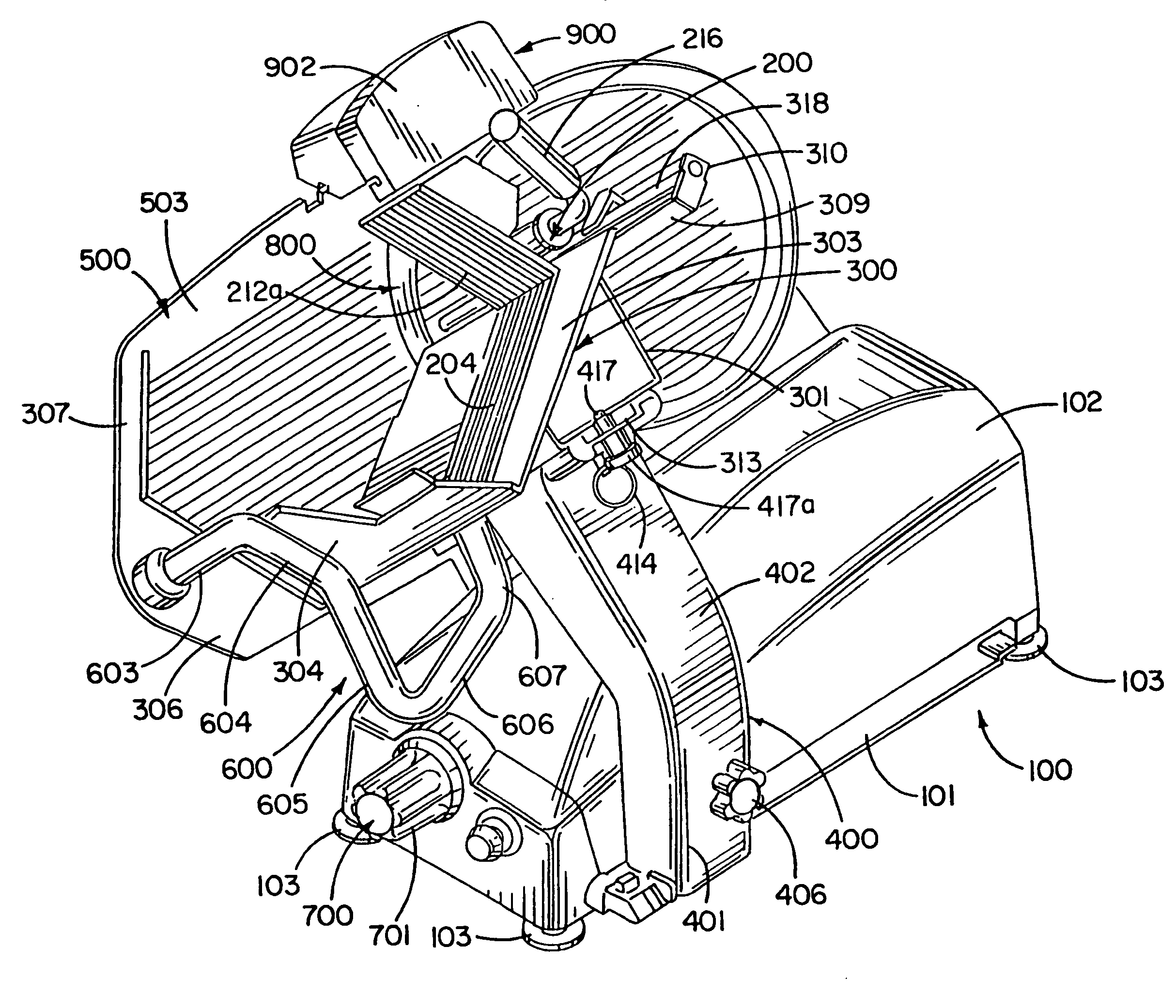
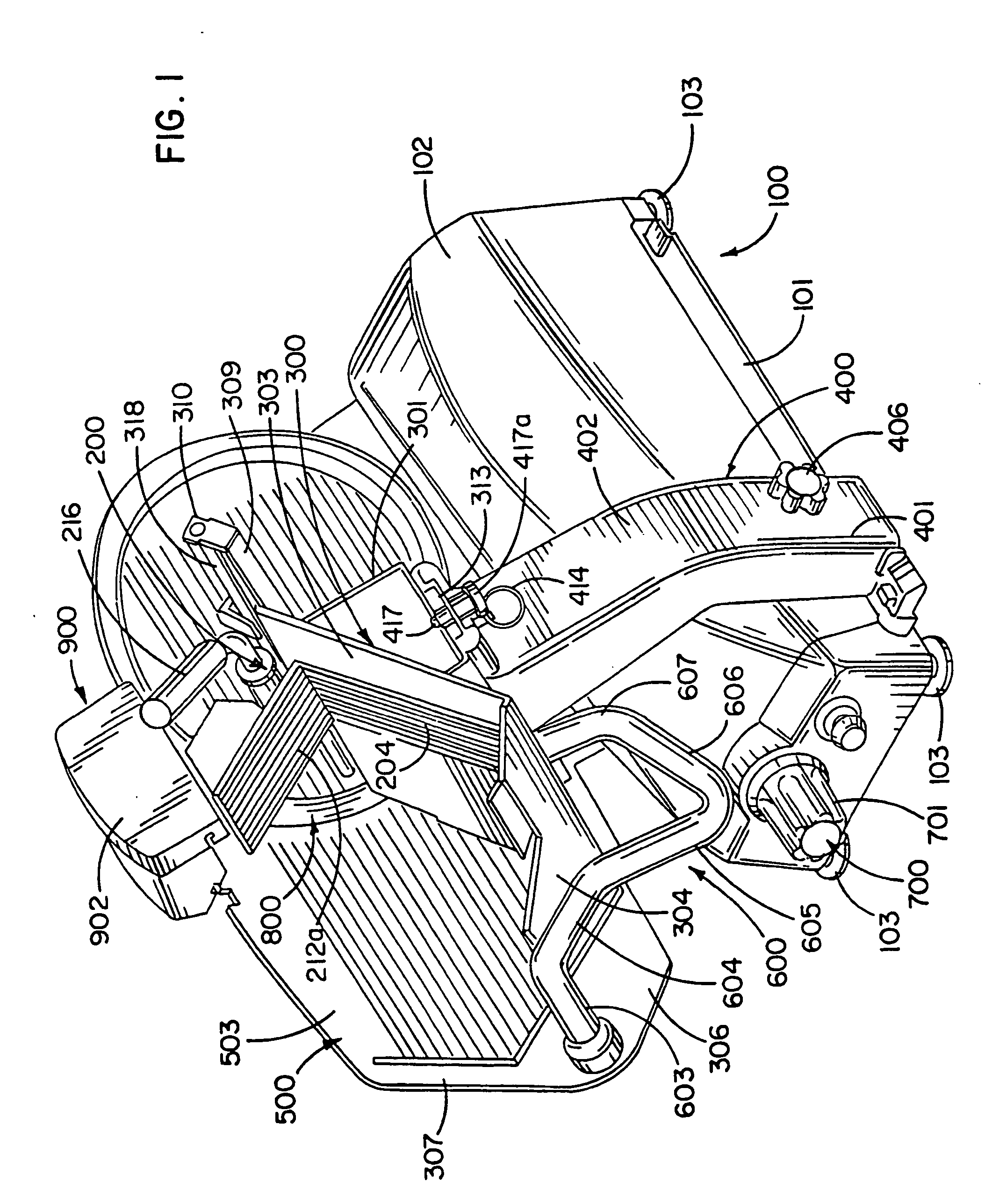
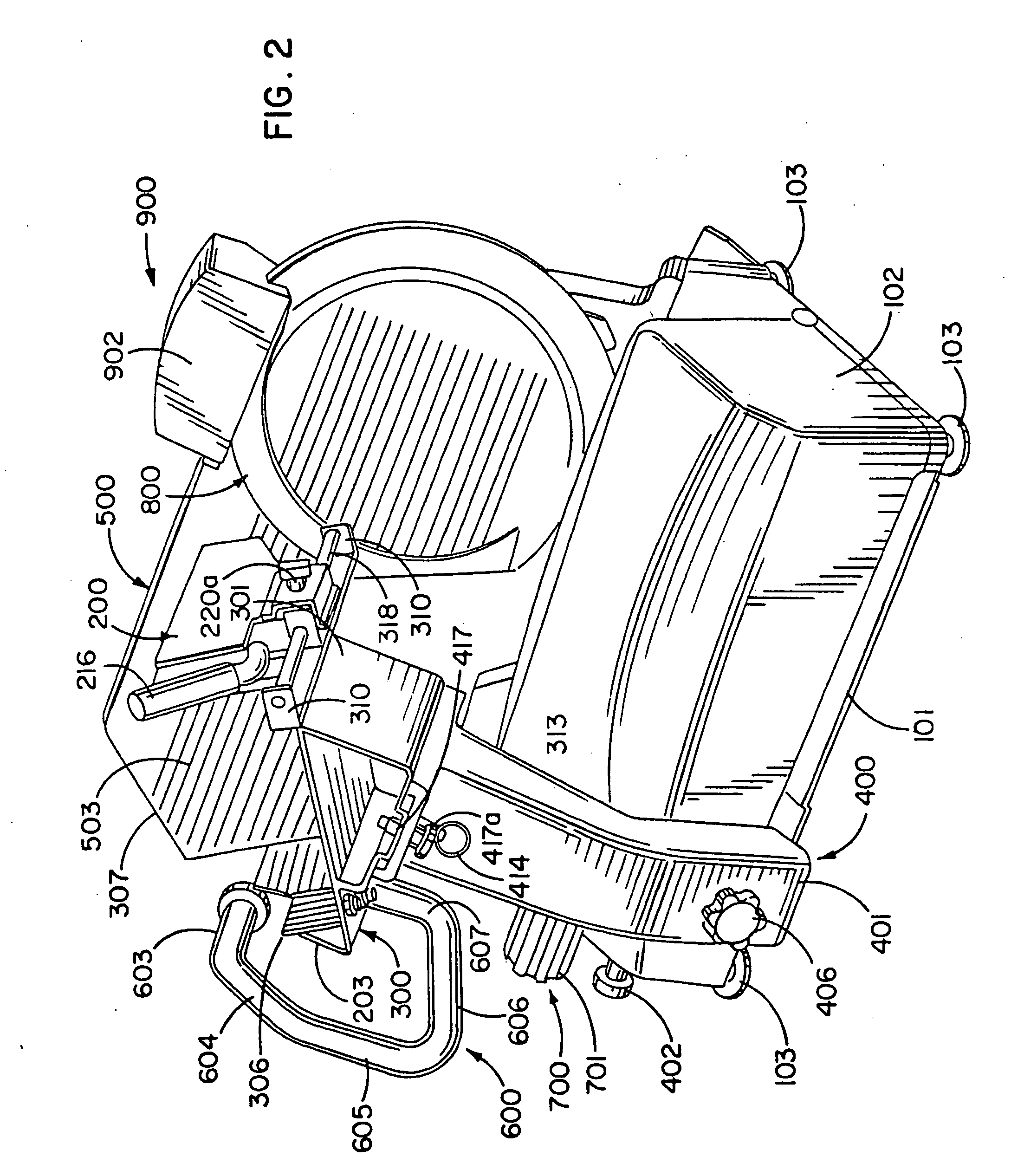
[0067] The slicing machine and various components according to the one embodiment of the invention are shown in FIGS. 1 through 8. In this embodiment, the slicing machine generally includes a housing 100, a pusher assembly 200, a table 300, a table arm 400, a gauge plate 500, a handle 600, an indexing assembly 700, a blade 800 and a sharpener assembly 900.

[0068] Base 100 generally includes a first portion 101, a cover 102 and a plurality of feet 103 for supporting the slicing machine on a surface, such as a counter.

[0069] Table arm 400 (FIGS. 13 and 14) generally includes, in the embodiment shown, a generally hollow arm having a first portion 401 and a second portion 402 defining an interior cavity 403. Portions 401 and 402 are disposed at an angle to one another. Arm 400 includes a pair of openings 404 which are used to pivotally attach arm 400 to a carriage assembly located within base 100 of the slicing machine such that arm 400, table 300, pusher assembly 200 and handle 600 ma...


PUM

PropertyMeasurementUnit
timeaaaaaaaaaa
angleaaaaaaaaaa
thicknessaaaaaaaaaa

Abstract

An ergonomically designed food slicing machine including a rotatable blade (800, 2800) for slicing bulk food product, a motor (1400, 3400) operably connected to the rotating blade (800, 2800), and a base (100) portion located below the rotatable blade (800, 2800) which defines a food slice receiving area. The machine may be provided with a sliced food receptable operably connected to a scale (3900), a visible indicia (3502) correlating to the distance between the gauge plate (2500) and rotatable blade (2800), a blade sharpening assembly (900, 2900), a sled (200) for securing the food product and an operator adjusted optimum stroke setting system for automatic operation of the slicing machine.

Description

FIELD OF THE INVENTION [0001] The present invention relates to a slicing machine, such as the kind often used to slice deli meats, cheeses and similar items. The invention also relates to various parts and components of such a slicing machine. BACKGROUND OF THE INVENTION [0002] Various commercial meat slicing machinery are currently used by delicatessens, supermarkets, and butcher shops to slice bulk meat or cheese product for sale to retail customers. The slicer operator typically stands in front of the machine and adjusts the slicer to provide slices of pre-determined thickness by rotating a knob having numerical indicia of the slice thickness. The rotation of the knob adjusts the distance between a gauge plate and a slicing blade to correlate with the numerical value selected for slice thickness. The slicer operator typically stands in front of the machine with the product to be sliced held on a movable table on the right side of the operator. The operator turns on the blade moto...

Claims


Application Information

Patent Timeline
Patent Type & Authority Applications(United States)
IPC IPC(8): B26D1/29
CPCB24B3/463B26D1/143B26D5/00B26D7/01B26D7/0616B26D7/12B26D7/22B26D7/225B26D7/2635B26D7/30B26D2210/02Y10S83/01Y10S83/932Y10T83/0538Y10T83/303Y10T83/313Y10T83/626Y10T83/6515Y10T83/6516Y10T83/7709
Inventor CHASE, KENT BRADLEYVERHALEN, AMYBIBA, SCOTTSULLIVAN, SCOTTLINDEMAN, WILLIAMROBERTS, SHELDON
Owner BERKEL & CONTRACTORS
Why Eureka
Try Eureka