Three terminal magnetic sensor having an in-stack longitudinal biasing layer structure in the collector region and a pinned layer structure in the emitter region

a three-terminal magnetic sensor and collector technology, applied in the field of three-terminal magnetic sensors, can solve the problems of troublesome, incongruous magnetic field through the free layer between the first and second sides, and prone to failure or damage in the base region, so as to reduce the base resistance, and reduce the emitter resistance

Inactive Publication Date: 2006-07-13
WESTERN DIGITAL TECH INC
View PDF33 Cites 10 Cited by
  • Summary
  • Abstract
  • Description
  • Claims
  • Application Information

AI Technical Summary

Benefits of technology

[0014]FIG. 4 is a perspective view of a TTM having a metal layer formed so as to reduce the base resistance;
[0015]FIG. 5 is a perspective view of another TTM having an alternative metal layer formed so as to reduce the base resistance;
[0016]FIG. 6 is a perspective view of yet another TTM having an alternative metal layer formed so as to reduce the emitter resistance;

Problems solved by technology

Thus, as the sense current passes through the base region from the emitter lead to the base lead, the base region may be prone to failure or damage (e.g. it could “blow” like a fuse).
Further, a relatively large resistance for the base region raises the noise floor for the TTM, such that a much larger input signal would be required for suitable operation.
Unfortunately, the magnetic field through the free layer between the first and second sides is not uniform since a portion of the magnetization is lost in a central region of the free layer to the shields.
This is especially troublesome when the track width of the TTM may be in sub-micron dimensions.

Method used


Image

  • Three terminal magnetic sensor having an in-stack longitudinal biasing layer structure in the collector region and a pinned layer structure in the emitter region
  • Three terminal magnetic sensor having an in-stack longitudinal biasing layer structure in the collector region and a pinned layer structure in the emitter region
  • Three terminal magnetic sensor having an in-stack longitudinal biasing layer structure in the collector region and a pinned layer structure in the emitter region

Examples


Embodiment Construction

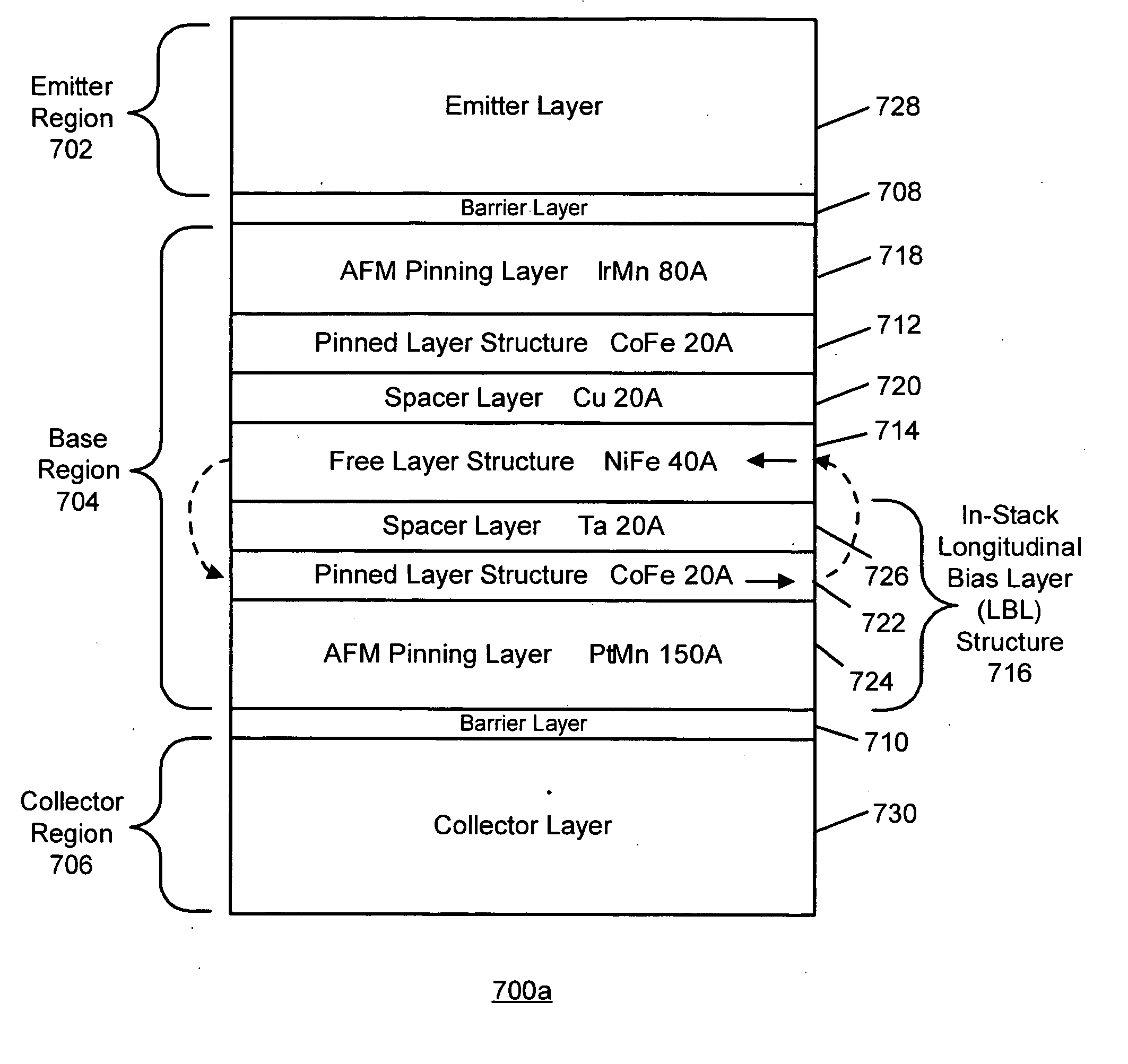
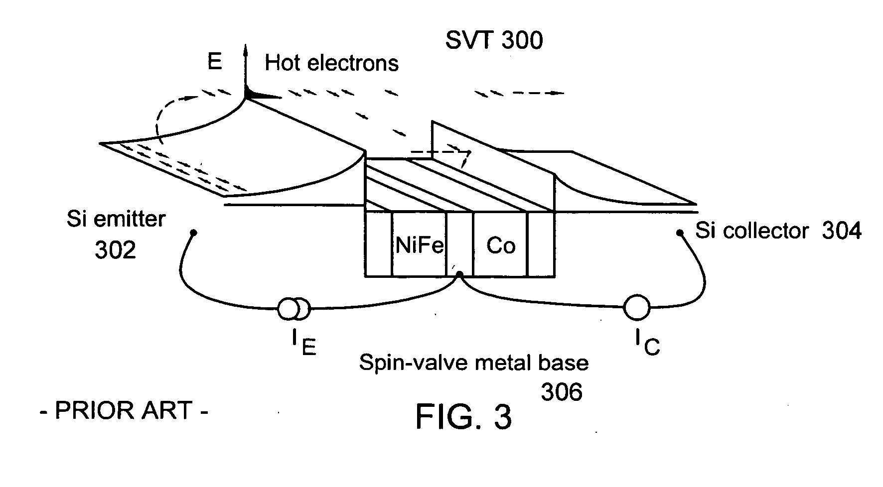
[0032] In one illustrative embodiment of the present application, a three terminal magnetic sensor (TTM) suitable for use in a magnetic head has a base region, a collector region, and an emitter region. A first barrier layer separates the emitter region from the base region, and a second barrier layer separates the collector region from the base region. A sensing plane is defined along sides of the base region, the collector region, and the emitter region. The base region consists of a free layer structure so as to have a relatively small thickness. A pinned layer structure is made part of the emitter region. An in-stack longitudinal biasing layer (LBL) structure which magnetically biases the free layer structure is made part of the collector region. In one variation, the emitter region has the in-stack LBL structure and the collector region has the pinned layer structure. The TTM may comprise a spin valve transistor (SVT), a magnetic tunnel transistor (MTT), or a double junction st...


PUM

PropertyMeasurementUnit
electrical resistanceaaaaaaaaaa
thicknessaaaaaaaaaa
electrical resistanceaaaaaaaaaa

Abstract

In one illustrative example, a three terminal magnetic sensor (TTM) suitable for use in a magnetic head has a base region, a collector region, and an emitter region. A first barrier layer separates the emitter region from the base region, and a second barrier layer separates the collector region from the base region. A sensing plane is defined along sides of the base region, the collector region, and the emitter region. The base region consists of a free layer structure so as to have a relatively small thickness. A pinned layer structure is made part of the emitter region. An in-stack longitudinal biasing layer (LBL) structure which magnetically biases the free layer structure is made part of the collector region. In one variation, the emitter region has the in-stack LBL structure and the collector region has the pinned layer structure. The TTM may comprise a spin valve transistor (SVT), a magnetic tunnel transistor (MTT), or a double junction structure.

Description

BACKGROUND [0001] 1. Field of the Technology [0002] This invention relates generally to three terminal magnetic sensors (TTMs) suitable for use in magnetic heads, which includes spin valve transistors (SVTs), magnetic tunnel transistors (MTTs), or double junction structures. [0003] 2. Description of the Related Art [0004] Magnetoresistive (MR) sensors have typically been used as read sensors in hard disk drives. An MR sensor detects magnetic field signals through the resistance changes of a read element, fabricated of a magnetic material, as a function of the strength and direction of magnetic flux being sensed by the read element. The conventional MR sensor, such as that used as a MR read head for reading data in magnetic recording disk drives, operates on the basis of the anisotropic magnetoresistive (AMR) effect of the bulk magnetic material, which is typically permalloy. A component of the read element resistance varies as the square of the cosine of the angle between the magnet...

Claims


Application Information

Patent Timeline
Patent Type & Authority Applications(United States)
IPC IPC(8): G11B5/33G11B5/127H01L29/82H01L43/00
CPCB82Y25/00G01R33/093G11B5/3932H01L29/66984H01L43/08H10N50/10
Inventor CHILDRESS, JEFFREY R.LILLE, JEFFREY S.
Owner WESTERN DIGITAL TECH INC
Why Eureka
Try Eureka