Three terminal magnetic sensor having an in-stack longitudinal biasing layer structure in the collector or emitter region

Inactive Publication Date: 2006-07-13
HITACHI GLOBAL STORAGE TECH NETHERLANDS BV
View PDF19 Cites 9 Cited by
  • Summary
  • Abstract
  • Description
  • Claims
  • Application Information

AI Technical Summary

Benefits of technology

[0014]FIG. 4 is a perspective view of a TTM having a metal layer formed so as to reduce the base resistance;
[0015]FIG. 5 is a perspective view of another TTM having an alternative meta

Problems solved by technology

Thus, as the sense current passes through the base region from the emitter lead to the base lead, the base region may be prone to failure or damage (e.g. it could “blow” like a fuse).
Further, a relatively large resistance for the base region raises the noise floor for the TTM, such that a much larger input signal would be requ

Method used


Image

  • Three terminal magnetic sensor having an in-stack longitudinal biasing layer structure in the collector or emitter region
  • Three terminal magnetic sensor having an in-stack longitudinal biasing layer structure in the collector or emitter region
  • Three terminal magnetic sensor having an in-stack longitudinal biasing layer structure in the collector or emitter region

Examples


Embodiment Construction

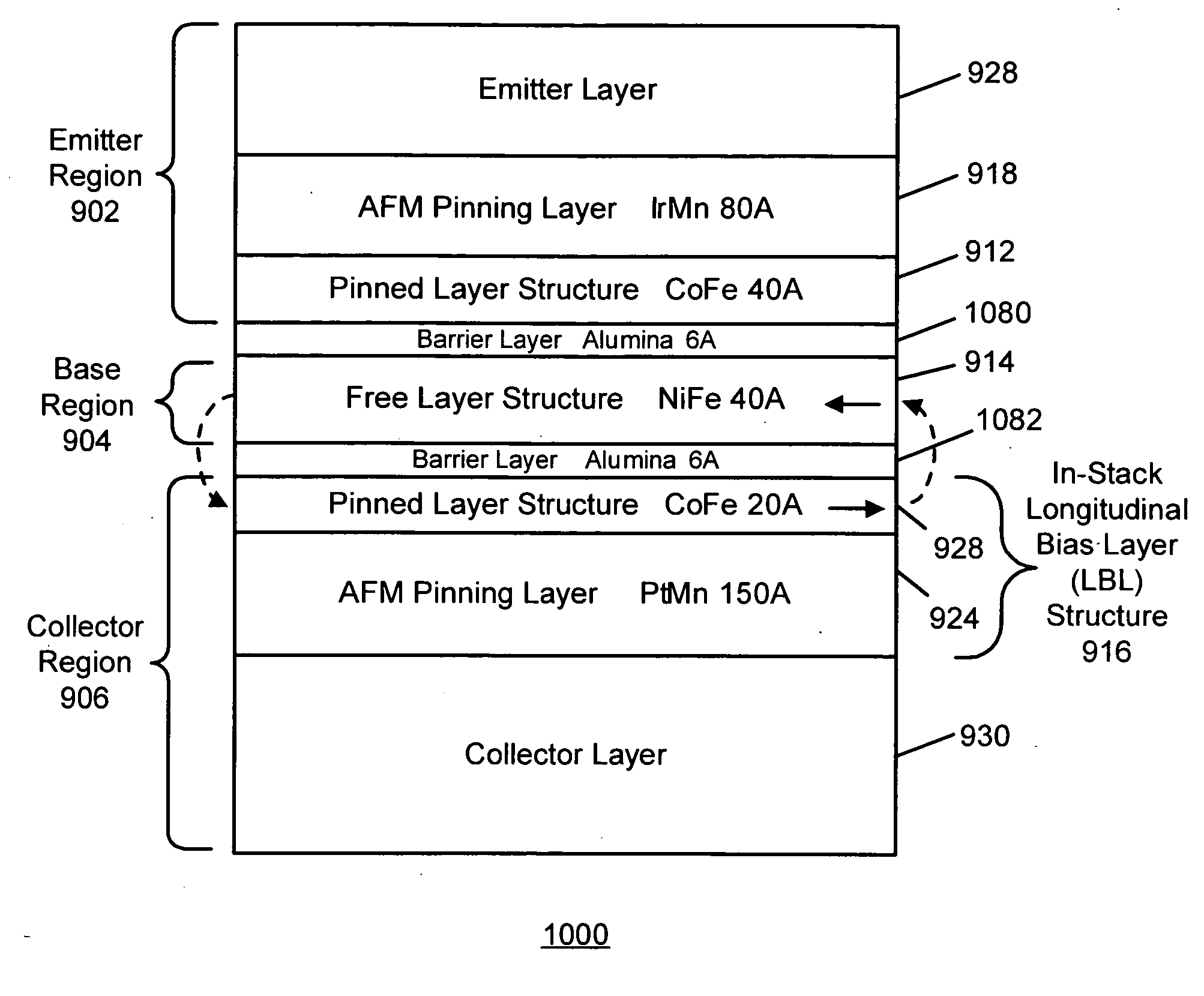
[0032] In one illustrative example of the present invention, a three terminal magnetic sensor (TTM) suitable for use in a magnetic head has a base region, a collector region, and an emitter region. A first barrier layer is located between the emitter region and the base region, and a second barrier layer is located between the collector region and the base region. An air bearing surface (ABS) sensing plane of the TTM is defined along sides of the base region, the collector region, and the emitter region. The base region has a free layer structure, a pinned layer structure adjacent the first barrier layer, and a non-magnetic spacer layer located between the free layer structure and the pinned layer structure. The collector region comprises an in-stack longitudinal biasing layer structure which magnetically biases the free layer structure, where the second barrier layer serves as a non-magnetic spacer layer for the in-stacking biasing layer structure. In one variation, the layers are ...


PUM


Abstract

In one illustrative example, a three terminal magnetic sensor (TTM) suitable for use in a magnetic head has a base region, a collector region, and an emitter region. A first barrier layer is located between the emitter region and the base region, and a second barrier layer is located between the collector region and the base region. A sensing plane is defined along sides of the base region, the collector region, and the emitter region. The base region has a free layer structure, a pinned layer structure adjacent the first barrier layer, and a non-magnetic spacer layer located between the free layer structure and the pinned layer structure. The collector region comprises an in-stack longitudinal biasing layer (LBL) structure which magnetically biases the free layer structure, where the second barrier layer serves as a non-magnetic spacer layer for the in-stacking biasing layer structure. In one variation, the layers are inverted such that the emitter region has the in-stack LBL structure. The TTM may comprise a spin valve transistor (SVT), a magnetic tunnel transistor (MTT), or a double junction structure.

Description

BACKGROUND [0001] 1. Field of the Technology [0002] This invention relates generally to three terminal magnetic sensors (TTMs) suitable for use in magnetic heads, which includes spin valve transistors (SVTs), magnetic tunnel transistors (MTTs), or double junction structures. [0003] 2. Description of the Related Art [0004] Magnetoresistive (MR) sensors have typically been used as read sensors in hard disk drives. An MR sensor detects magnetic field signals through the resistance changes of a read element, fabricated of a magnetic material, as a function of the strength and direction of magnetic flux being sensed by the read element. The conventional MR sensor, such as that used as a MR read head for reading data in magnetic recording disk drives, operates on the basis of the anisotropic magnetoresistive (AMR) effect of the bulk magnetic material, which is typically permalloy. A component of the read element resistance varies as the square of the cosine of the angle between the magnet...

Claims


Application Information

Patent Timeline
IPC IPC(8): G11B5/33G11B5/127G11B5/147H01L29/82H01L43/00
CPCB82Y25/00G01R33/093G11B5/3903G11B5/3932H01L29/66984H01L43/08H10N50/10
Inventor CHILDRESS, JEFFREY R.LILLE, JEFFREY S.
Owner HITACHI GLOBAL STORAGE TECH NETHERLANDS BV
Why Eureka
Try Eureka