Laser temperature performance compensation

a technology of performance compensation and laser, applied in lasers, laser cooling arrangements, laser details, etc., can solve the problems of preventing the laser control system from determining the amplitude of data transmission light pulses, unable to provide adequate feedback information to adjust the magnitude of optical pulses, etc., to maximize signal transmission reliability and calibrate and stabilize bias and modulation currents

Inactive Publication Date: 2006-07-13
TECEY SOFTWARE DEV KG +1
View PDF6 Cites 32 Cited by
  • Summary
  • Abstract
  • Description
  • Claims
  • Application Information

AI Technical Summary

Benefits of technology

[0010] The method in this invention calibrates and stabilizes the bias and modulation currents. The threshold needed to turn on the laser is determined and a minimum DC bias current is chosen above the threshold. A value for the temperature drift model of the threshold current is determined and the value is stored in the Digital Controller (111) memory. Temperature coefficients for other parameters are stored in the Digital Controller (111). Once the system is in the field, the control system utilizes the photodiode sensor to continuously adjust the value of the average laser current to a fixed value above the minimum laser threshold. With the use of various algorithms, the value of the optical power corresponding to the logic one is adjusted to maximize signal transmission reliability.

Problems solved by technology

This type of performance poses a problem in determining the amplitude of the optical pulses for transmitting information since in some cases the photodiode will not generate significant output in response to the ac power output representing the data transmission.
Sensing the power with slow photodiodes poses a problem because only the average power of the laser is sensed due to the low frequency response of the photodiode.
This situation prevents the laser control system from determining the amplitude of the data transmission light pulses.
Thus, adequate feedback information will not be available to adjust the magnitude of optical pulses representing the data.
The optical output will not be properly controlled and the Extinction Ratio and Bit Error Rate (BER) will change with temperature and well as with aging.

Method used


Image

  • Laser temperature performance compensation
  • Laser temperature performance compensation
  • Laser temperature performance compensation

Examples


Embodiment Construction

[0015] The above-mentioned unresolved problems related to laser sensing power are overcome by the present invention.

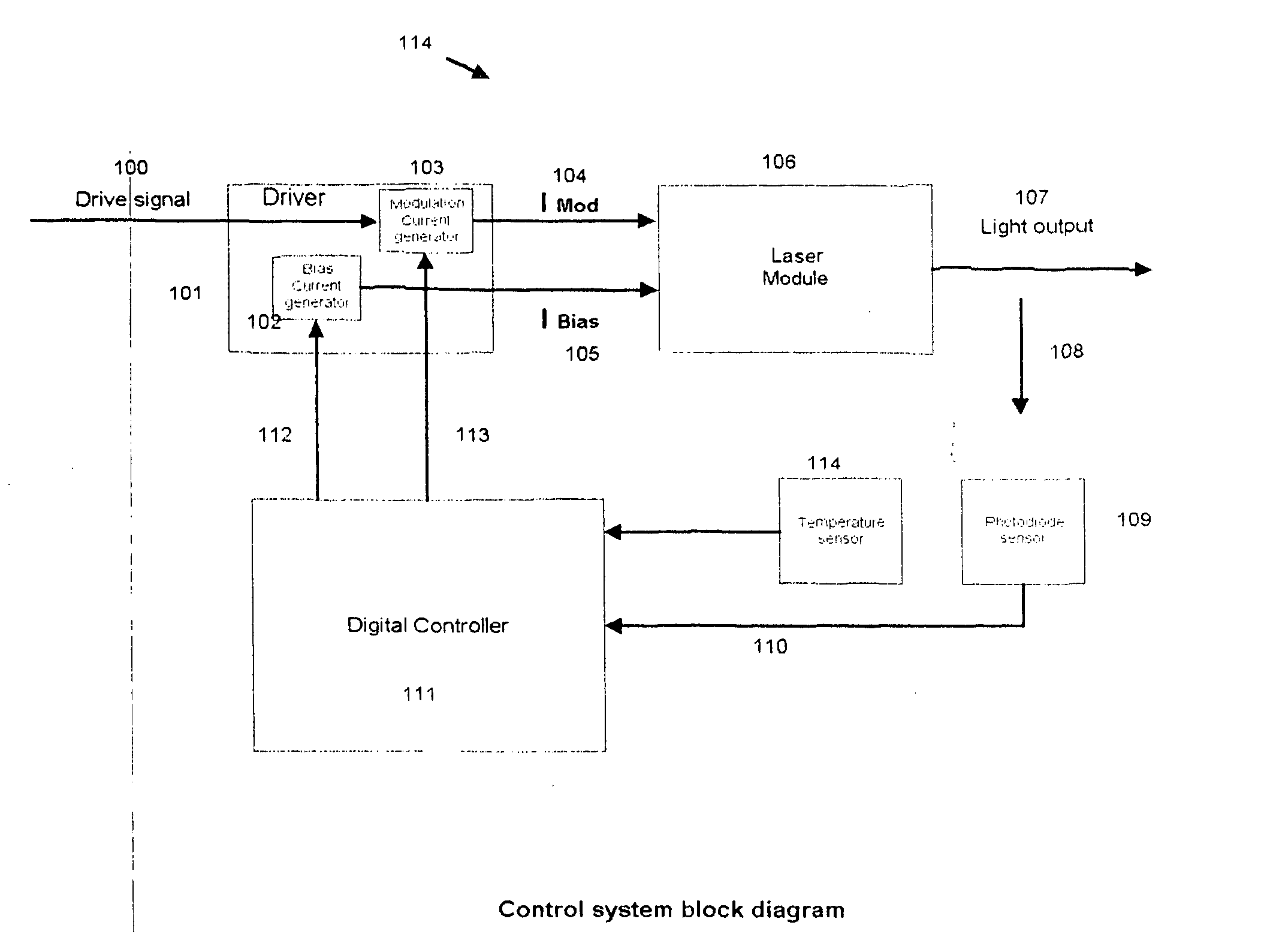
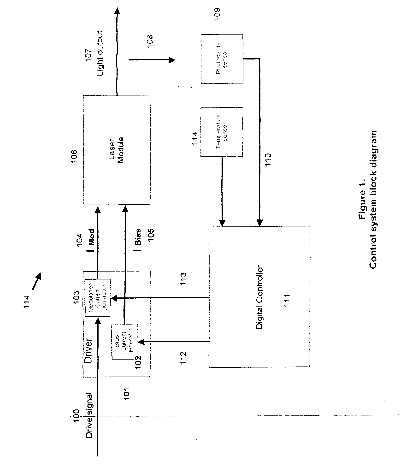
[0016]FIG. 1 shows a block diagram for a Laser Control System (114). The system consists of a drive Signal Input (100) applied to a Laser Module Driver (101), which contains a Bias Current Generator (102) and a Modulation Current Generator (103). The current generators are controlled by Bias Control Signal (112) and Modulation Control Signal (113). The Driver (101) produces Modulation Current (104) and Bias Current (105), which are applied to the Laser Module (106). The Laser Module (106) in turn produces Light Output (107). The magnitude of the Light Output (107) bears a relationship to the magnitude of the Modulation Current (104) and the Bias Current (105). A portion of the Light Output (107) from the laser is sensed. This constitutes the Optical Power Sense (108), which is coupled to a Photodiode Sensor (109). The Photodiode Sensor Output (110) is connected to a D...


PUM


Abstract

The invention presents a method that calibrates the laser optical power in a continuous manner without disrupting the flow of information in the optical communications link. The method utilizes knowledge of the measured value of the laser optical power and makes necessary adjustments to optimize the values of the Extinction Ratio, Bit Error Rate and to compensate for aging. The method utilizes knowledge of the temperature from a sensor and mathematical models, which contain parameters which are updated for a specific laser configuration.

Description

CROSS REFERENCES TO RELATED APPLICATIONS [0001] This application is a continuation in part application for copending U.S. patent application Ser. No. 09 / 724,692 filed on Nov. 28, 2000, entitled “Electro-Optic System and Controller and Method of Operation,” which in turn is a continuation in part of application Ser. No. 09 / 472,709 filed on Dec. 24, 1999, entitled “Electro-Optic Interface System and Method of Operation,” now U.S. Pat. No. 6,446,867 B1. This application is a conversion of provisional application Ser. No. 60 / 348,967, filed Jan. 14, 2002, entitled “Laser Power Sensing Methods.”REFERENCE TO OTHER APPLICATIONS [0002] This application is a continuation in part application for co-pending U.S. patent application Ser. No. 09 / 724,692 filed on Nov. 28, 2000, titled “Electro-Optic System Controller and Method of Operation”. This utility application is also filed based on provisional application 60 / 348,967 filed Jan. 14, 2002, entitled “Laser Power Sensing Methods.”BACKGROUND [000...

Claims


Application Information

Patent Timeline
Patent Type & Authority Applications(United States)
IPC IPC(8): H01S3/04
CPCH01S5/042H01S5/0427H01S5/0617H01S5/06812H01S5/0683
Inventor SANCHEZ, JORGE
Owner TECEY SOFTWARE DEV KG
Why Eureka
Try Eureka