Eureka AIR delivers breakthrough ideas for toughest innovation challenges, trusted by R&D personnel around the world.

Method for dewatering water-containing coal

Inactive Publication Date: 2006-07-20
KATAYAMA +1
View PDF13 Cites 10 Cited by
  • Summary
  • Abstract
  • Description
  • Claims
  • Application Information

AI Technical Summary

Benefits of technology

[0024] The present invention provides a novel method for dewatering which is capable of obtaining dewatered coal which is inhibited from reabsorbing water after dewatering and is inhibited from absorbing oxygen after dewatering. Therefore, according to the method, a mixture (water slurry) having proper viscosity and water content, which contains water which is removed from water-containing coal and the coal from which the water is removed, dewatered coal inhibited from spontaneous firing after dewatering and a briquette constituted of a mixture containing the coal and bitumen can be manufactured at low cost. Low-rank coal such as brown coal which is buried in large amount but can be used only in the nearby coalfields due to spontaneous firing after being dried can be effectively used. DESCRIPTION OF THE PREFERRED EMBODIMENTS
[0025] In the present invention, the water-containing coal which is subjected to dewatering is not particularly limited. For example, low-rank water-containing coals such as brown coal, lignite and sub-bituminous coal are cited. For the water content of the water-containing coal, calculated on the basis of the water-containing coal, the upper limit is preferably 85 weight %, more preferably 70 weight %, and the lower limit is preferably 25 weight %, more preferably 30 weight %, and even more preferably 40 weight %. The brown coal with the water content of 40 to 70 weight %, calculated on the basis of the water-containing coal, is used particularly preferably. As for the water-containing coal of which water content exceeds the above described upper limit, it is preferable to remove the water therefrom in advance by pressurization by, for example, a roll press or the like, before or after the following pulverization to bring the water content into the above described range.
[0026] The water-containing coal is preferably used by being pulverized into a predetermined particle size. As for the particle size, the upper limit is preferably 200 meshes, more preferably 150 meshes, and even more preferably 100 meshes. The lower limit is preferably 3 meshes, more preferably 30 meshes, and even more preferably 50 meshes. With the particle size of the water-containing coal of less than the above described lower limit, the coal easily sediments when it is converted into a water slurry, and with the particle size exceeding the above described upper limit, the viscosity of the water slurry increases and extra power is consumed for pulverization.
[0027] In the present invention, the water-containing coal is introduced into a sealed vessel and dewatered. The sealed vessel should be capable of heating the water-containing coal under pressurization and capable of applying a shearing force to the water-containing coal. For example, a kneader having a screw type stirring blade of a single shaft or a twin shaft, preferably a twin shaf0t, or, for example, a kneader including a screw used in a so-called screw feeder for making ground meat or ground fish can be used. The sealed vessel may be of either a batch type or a continuous type. Any continuous type sealed vessel, that can continuously carry out loading of the water-containing coal and withdrawing of the dewatered coal, and withdrawing of gaseous or liquid water while keeping the predetermined conditions of the present invention, is suitably used.
[0028] As for the heating temperature, the upper limit is 350° C., preferably 300° C., and more preferably 250° C., and the lower limit is 100° C., preferably 150° C., and more preferably 200° C. At the temperature exceeding the above described upper limit, the apparatus cost becomes extremely high, and at the temperature lower than the above described lower limit, the effect of the present invention by dewatering cannot be obtained. As for the heating time, the upper limit is preferably five hours, more preferably three hours, still more preferably one hour, and particularly preferably 30 minutes, and the lower limit is preferably 3 minutes, more preferably 5 minutes, and still more preferably 10 minutes. By the heating, heat of preferably 2300 kj at the maximum is given per 1 kg of water contained in the water-containing coal.
[0029] The lower limit of the pressure during heating is the pressure not less than saturated steam pressure at the temperature for the heating, preferably the pressure not less than the saturated steam pressure at the temperature for the heating +0.1 MPa, and more preferably the pressure not less than the saturated steam pressure at the temperature for the heating +0.2 MPa. By keeping the pressure, the water removed from the water-containing coal can be kept in the liquid state, and therefore, unnecessary latent heat of vaporization does not need to be given during dewatering. The upper limit of the pressure is preferably the saturation steam pressure at the temperature for the heating +1.0 MPa, more preferably the saturation steam pressure at the temperature for the heating +0.5 MPa, and still more preferably the saturation steam pressure at the temperature for the heating +0.3 MPa. However, the maximum pressure during the heating is preferably the saturation steam pressure at 350° C. which is the maximum value of the temperature for the heating +1.0 MPa (=17.8 MPa). The pressure exceeding the upper limit is not preferable, because there is not a large difference in the effect, and the apparatus cost becomes higher. The pressure during the heating can be adjusted by preferably using an inert gas, such as nitrogen and argon, for example, in addition to steam which occurs from the water-containing coal by heating.

Problems solved by technology

Therefore, the coal which is obtained by drying the water-containing coal has the risk of oxygen entering the pores during storage or transportation of the coal to cause slow oxidization reaction to cause spontaneous firing.
Therefore, such water-containing coal is utilized in extremely limited areas near coalfields under the present circumstances.
However, the decrease in the pore volume is not sufficient, and the above described problem is not solved sufficiently yet.
The mixture (water slurry) of the coal, which is dewatered by the above described methods, and water requires the water content which is twice to four times as high as that of the mixture of ordinary bituminous coal and water in order to obtain about the same viscosity as that of the mixture of ordinary bituminous coal and water, which is suitable for transportation, and therefore, is not economical.
The treatment cost of dewatering and draining of water accompanying the dewatering is high, and therefore, these methods are not put into actual use.

Method used


Image

  • Method for dewatering water-containing coal

Examples


example 1

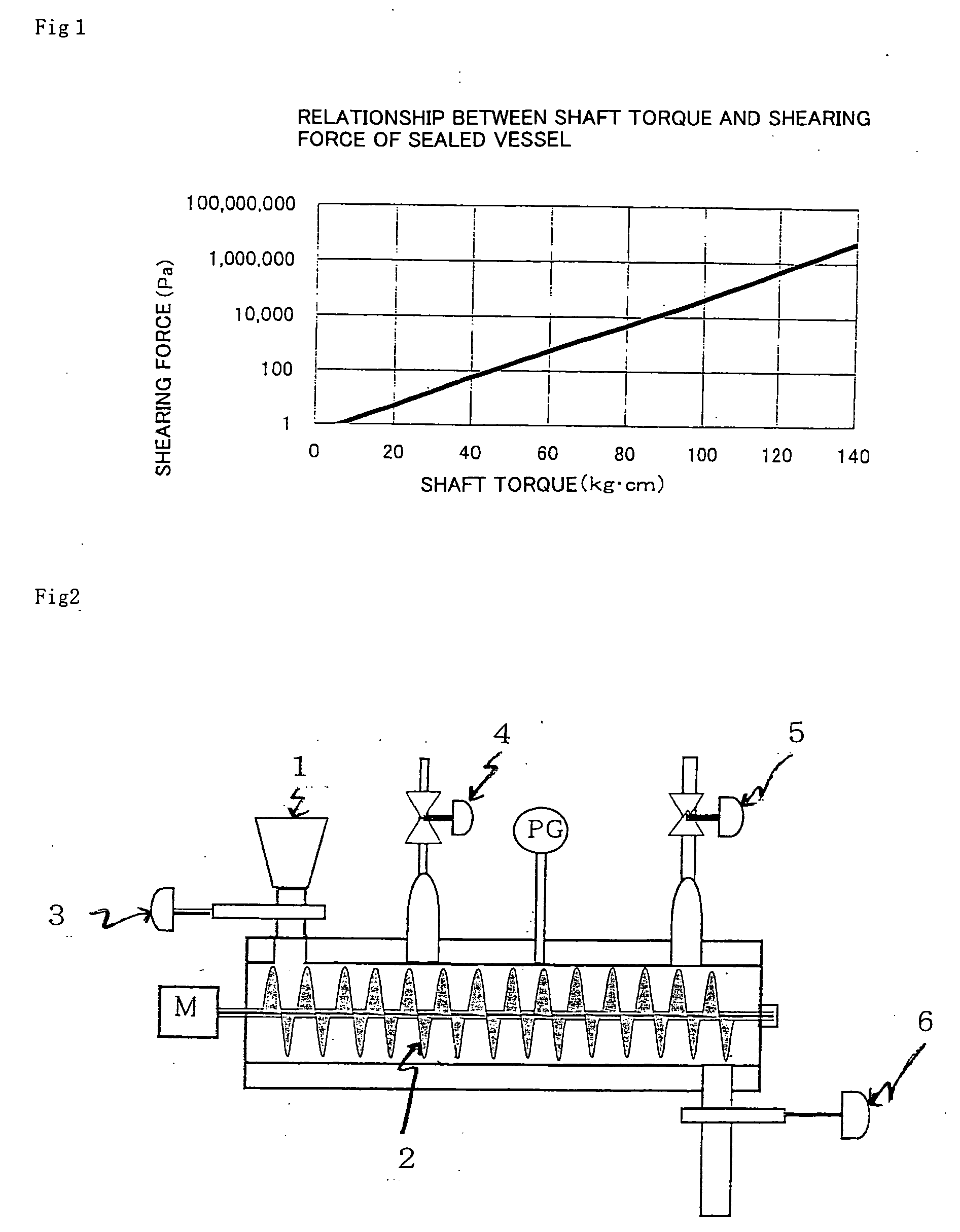
[0038] As the sealed vessel, the twin-shaft screw type kneader as shown in FIG. 2 was used. The effective internal volume of the vessel is 8 litters. In FIG. 2, reference numeral 1 designates a coal supply port, reference numeral 2 designates a screw, reference numeral 3 designates a valve, reference numeral 4 designates a steam extracting valve, reference numeral 5 designates an asphalt injecting valve, and reference numeral 6 designates a product removing valve. The brown coal having the above described properties were previously pulverized into 30 to 100 meshes. 10 kg of the pulverized brown coal was prepared in the vessel. Then, after the pressure inside the vessel was made 0.7 MPa with a nitrogen gas, heating was started while the screw was rotated to adjust the temperature to 170° C. Immediately after the temperature reached this temperature, the pressure inside the vessel was adjusted to 1 MPa, and the torque exerted on the stirring shaft was measured, and by using the relati...

example 2

[0040] Example 2 was carried out in the same manner as Example 1 except that heating was conducted at 200° C. under the pressure of 2 MPa for one hour and heating was conducted at 250° C. under the pressure of 4 MPa for one hour. The viscosities (20° C.) of the obtained water slurries were shown in the following Table 3.

TABLE 3Treatment temperature170° C.200° C.250° C.Viscosity (cP)10,0004,000800

[0041] From the result of Example 1, it is found out that with long treatment time, the water slurry with low viscosity is obtained. From the result of Example 2, it is found out that with the higher treatment temperature, the water slurry with lower viscosity is obtained. From the fact that the amount of water as the medium in the water slurry increased, it is obvious that dewatering of the brown coal advanced more as the viscosity of the water slurry reduced.

example 3

[0043] The single-shaft pressing / heating type kneading device having the stirring blade described in Japanese Patent Application Laid-open No. 2000-169274 was used. The brown coal shown in Table 1 was pulverized into 30 to 100 meshes. 15 kg of the pulverized brown coal was supplied in the tank of the device. Then, after the pressure inside the tank was made 0.7 MPa with a nitrogen gas, heating was started with the screw rotated, and the temperature was adjusted to 170° C. Immediately after the temperature reached this temperature, the pressure inside the tank was adjusted to 1 MPa, and the torque exerted on the stirring shaft was measured, and by using the relationship between the torque and shearing force prepared in advance, the shearing force was adjusted to 1 MPa. The treatment was conducted for an hour with the pressure, temperature and shearing force inside the tank kept at the above described values, and water was removed from the brown coal. Then, the tank was cooled to the ...


PUM


Abstract

A method for dewatering water-containing coal which includes heating the water-containing coal at a temperature of 100 to 350° C. under a pressure not less than a saturated steam pressure at the temperature for the heating, while applying a shearing force of 0.01 to 20 MPa to the coal, in a sealed vessel. The method is novel and allows the production of dewatered coal which is inhibited from reabsorbing water after dewatering and is also inhibited from absorbing oxygen after dewatering.

Description

FIELD OF THE INVENTION [0001] The present invention relates to a method for dewatering water-containing coal, a method for producing a water slurry of the dewatered coal, and a method for producing pulverized coal and briquette. BACKGROUND OF THE INVENTION [0002] Water-containing coal, for example, brown coal has a high water content and a number of relatively large pores in its structure. Even if the water-containing coal is pulverized and dried for use, the size and the number of the pores hardly change. Therefore, the coal which is obtained by drying the water-containing coal has the risk of oxygen entering the pores during storage or transportation of the coal to cause slow oxidization reaction to cause spontaneous firing. Therefore, such water-containing coal is utilized in extremely limited areas near coalfields under the present circumstances. [0003] The methods for dewatering water-containing coal, for example, brown coal by performing hydrothermal treatment for the coal at ...

Claims


Application Information

Patent Timeline
IPC IPC(8): C10L5/00C10L9/08
CPCC10L9/08
Inventor KATAYAMA, YUKUO
Owner KATAYAMA
Why Eureka
Eureka Blog
Learn More