Exhaust gas treatment system

a gas treatment system and exhaust gas technology, applied in the direction of separation processes, machines/engines, mechanical equipment, etc., can solve the problems of affecting the quality of exhaust gas treatment, and occupying a large space, so as to reduce the complexity and expense of manufacturing the exhaust system, and simplify the maintenance of the respective particulate separation device. , the effect of compact design

Active Publication Date: 2006-07-20
PUREM GMBH
View PDF3 Cites 60 Cited by
  • Summary
  • Abstract
  • Description
  • Claims
  • Application Information

AI Technical Summary

Benefits of technology

[0003] The present invention relates to the problem of providing means that will permit a compact design in particular and at the same time simple maintenance of the respective particulate separation device, e.g., a particulate filter, for an exhaust system of an internal combustion engine.
[0004] The present invention is based on the general idea of creating an exhaust gas treatment system comprised of two housings, namely a basic housing and an add-on housing which accommodate at least one inlet pipe, at least one outlet pipe, at least one SCR catalyst, at least one oxidizing catalyst, at least one particle separation device and at least one reducing agent feed device. The exhaust gas treatment system therefore has an extremely compact design. The inventive exhaust gas treatment system can be completely preassembled and can be installed in the exhaust system as a completely preassembled unit. This

Problems solved by technology

Such exhaust systems are comparatively complex due to the plurality of components and also take up a great deal of space.
In addition, during operation of the exhaust syste

Method used


Image

  • Exhaust gas treatment system
  • Exhaust gas treatment system
  • Exhaust gas treatment system

Examples


Embodiment Construction

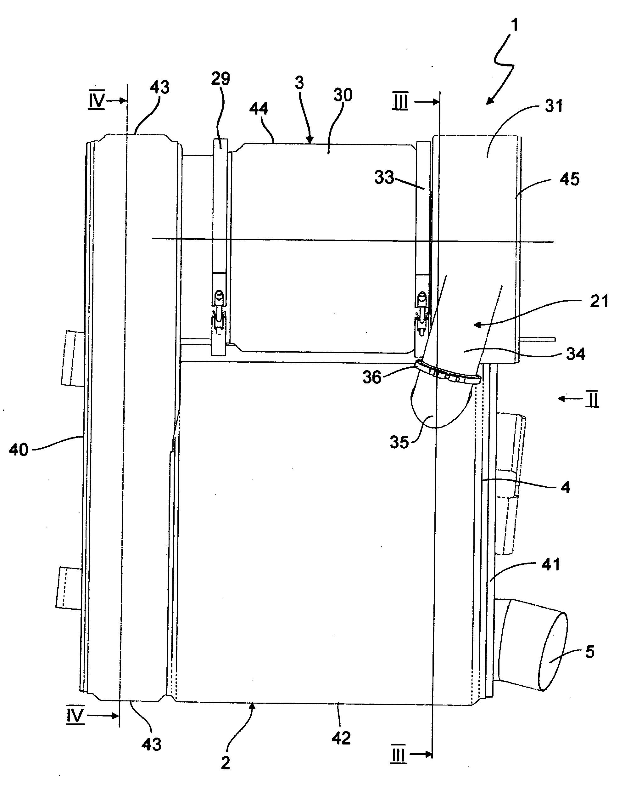
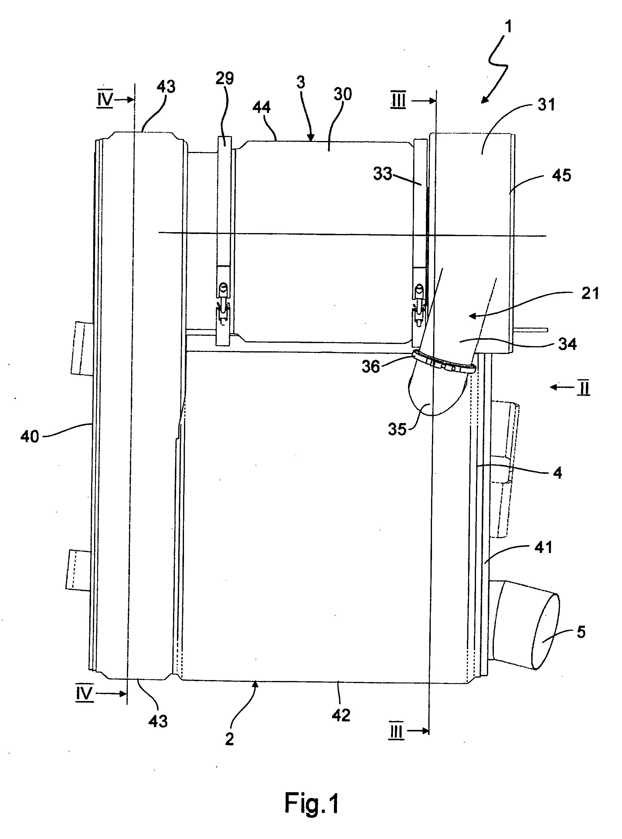
[0017] According to FIG. 1, an inventive exhaust gas treatment system 1 has a basic housing 2 and an add-on housing 3. The exhaust gas treatment system 1 is connectable to an exhaust system (not shown here) of an internal combustion engine, whereby the internal combustion engine, in particular a diesel engine, is preferably situated in a motor vehicle, preferably a commercial vehicle.

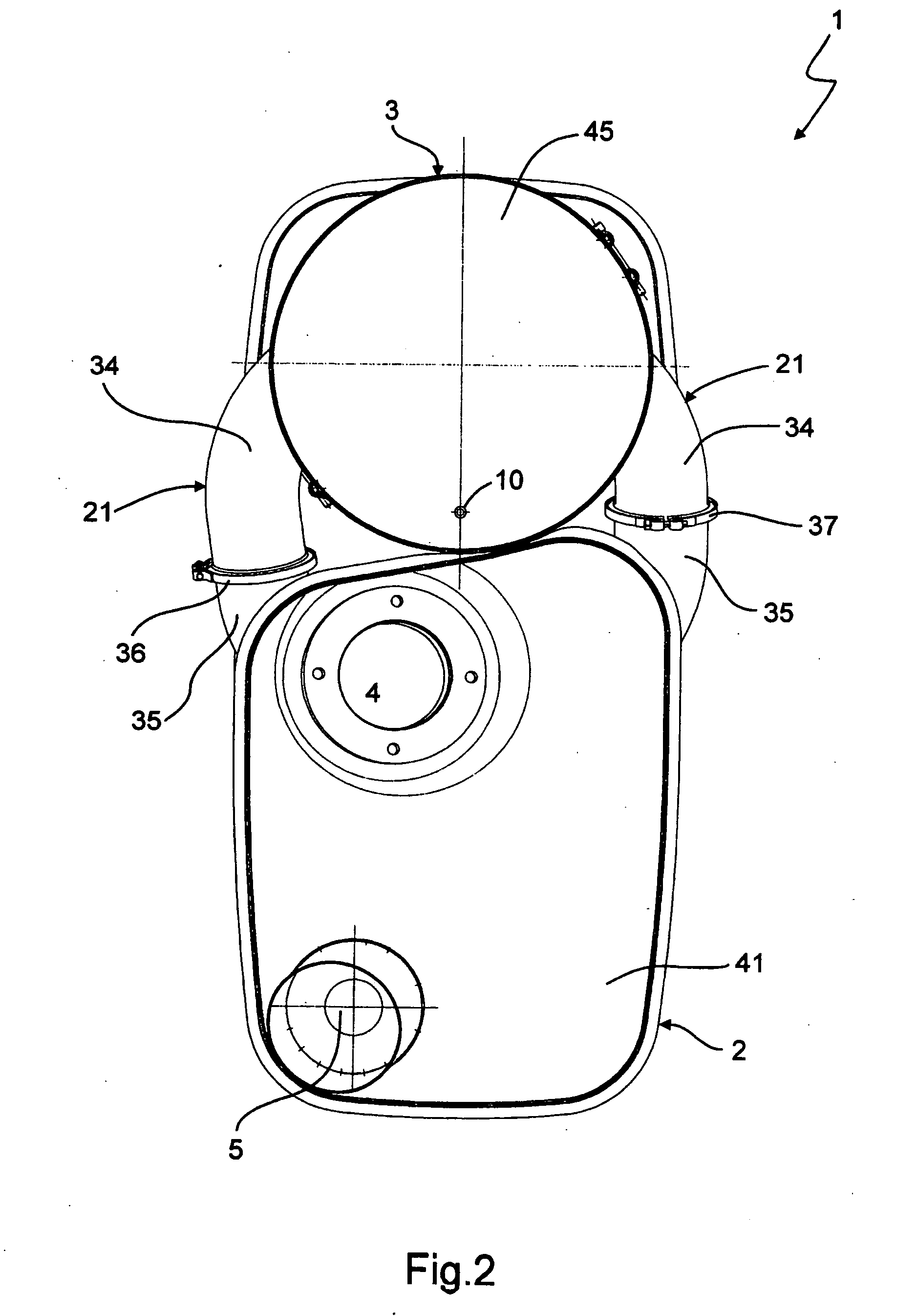
[0018] According to FIGS. 1 through 6, the exhaust gas treatment system 1 comprises in its housings 2 and 3 at least one inlet pipe 4 and at least one outlet pipe 5. Inlet pipe 4 and outlet pipe 5 are connectable to the exhaust system. The inlet pipe 4 leads into the basic housing 2 and the outlet pipe 5 leads out of the basic housing 2. In addition, at least one SCR catalyst 6 and at least one oxidizing catalytic converter 7 are arranged in the basic housing 2. In the present case several SCR catalysts 6, namely four SCR catalysts 6 are provided, with the flow passing through them in parallel. Accordi...


PUM

PropertyMeasurementUnit
Flow rateaaaaaaaaaa
Areaaaaaaaaaaa
Permeabilityaaaaaaaaaa

Abstract

The present invention relates to an exhaust gas treatment system for an exhaust system of an internal combustion engine, and comprises a basic housing and an add-on housing mounted thereon so it is at least partially detachable. The basic housing contains at least one inlet pipe which can be connected to the exhaust system and leads into the basic housing, at least one outlet pipe which can be connected to the exhaust system and leads out of the basic housing, at least one SCR catalyst and at least one oxidizing catalytic converter. The add-on housing contains at least one particle separation device and at least one reducing agent feed mechanism.

Description

FIELD OF THE INVENTION [0001] The present invention relates to an exhaust gas treatment system for an exhaust system of an internal combustion engine, in particular in a motor vehicle. BACKGROUND OF THE INVENTION [0002] It is known that to be able to comply with the ever more stringent exhaust standards for internal combustion engines, in particular for diesel engines, the respective exhaust system may be equipped with an oxidizing catalytic converter, a particulate filter and an SCR catalyst, where SCR stands for “selective catalytic reaction.” Upstream from this SCR catalyst, a suitable reducing agent, preferably urea, is sprayed into the exhaust stream. Then with the help of the reducing agent, effective degradation of nitrogen oxides is performed in the SCR catalyst. Such exhaust systems are comparatively complex due to the plurality of components and also take up a great deal of space. Therefore, there has been a search for the most compact possible means of achieving this obje...

Claims


Application Information

Patent Timeline
IPC IPC(8): F01N3/035
CPCF01N1/084F01N3/0335F01N3/035F01N3/2066F01N3/2885F01N13/141F01N2330/06F01N2330/14F01N2450/24F01N2450/30F01N2470/18F01N2470/22F01N2610/02F01N2610/1453Y02T10/24F01N13/017F01N13/0097Y02T10/12Y02A50/20
Inventor BUHMANN, RUDOLFLEHNEN, RAINERWIELAND, ARTHUR
Owner PUREM GMBH
Why Eureka
Try Eureka