Hydraulic drive system
a technology of hydraulic drive and drive shaft, which is applied in the direction of fluid coupling, servomotor, coupling, etc., can solve the problems of inflexibility in implementing different control strategies, loss of energy, and inefficient valve systems in terms of energy dissipation across valves
- Summary
- Abstract
- Description
- Claims
- Application Information
AI Technical Summary
Benefits of technology
Problems solved by technology
Method used
Image
Examples
Embodiment Construction
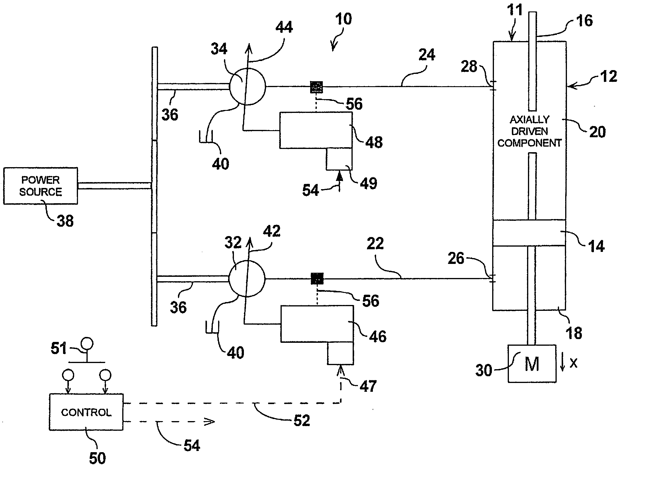
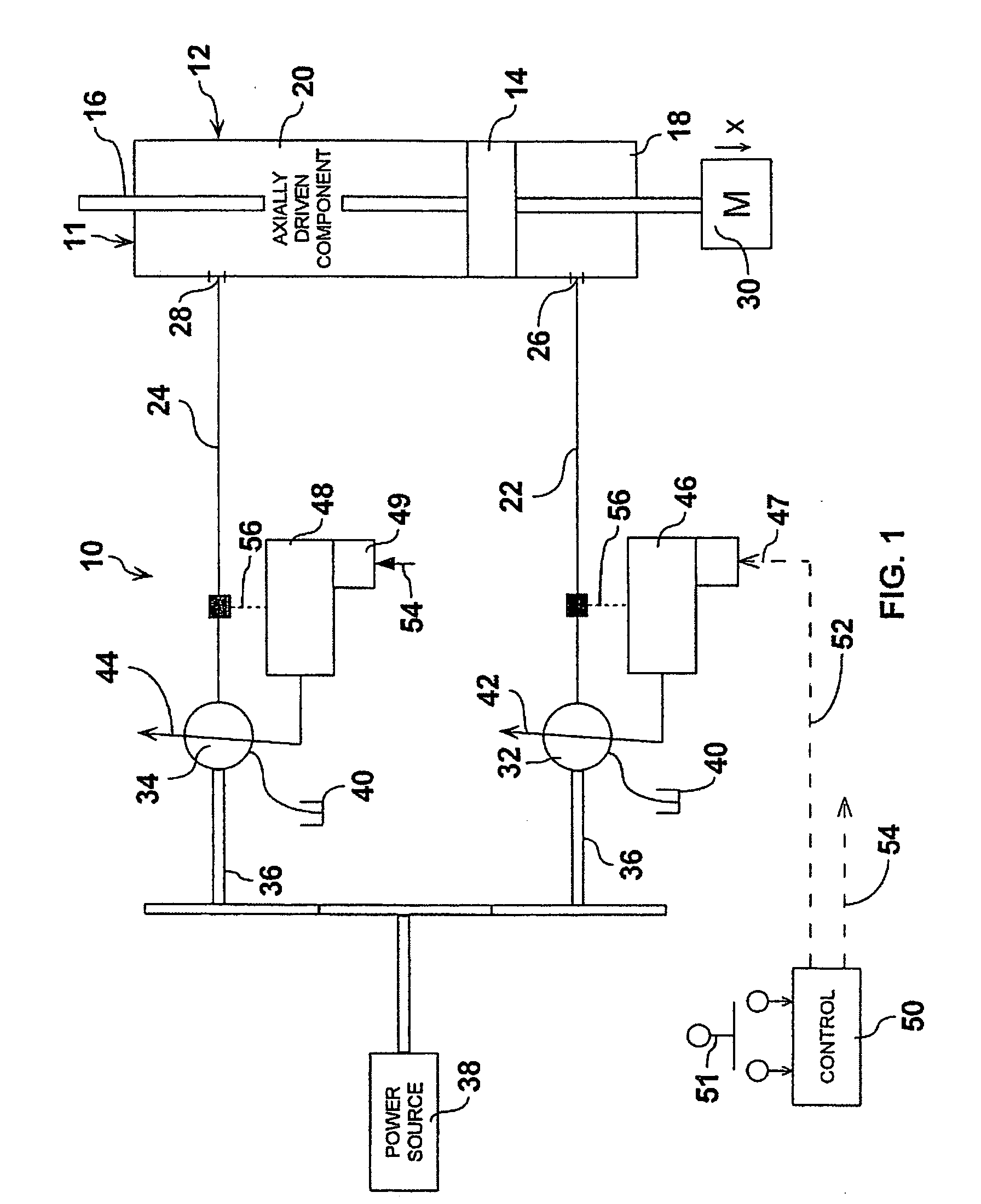
[0020] Referring therefore to FIG. 1, a hydraulic drive system 10 includes an actuator 11 having a cylinder 12 with a piston 14 supported within the cylinder 12. The piston 14 is connected to a piston rod 16 that extends from opposite ends of the cylinder 12. The piston 14 subdivides the cylinder 12 into chambers 18 and 20 which are connected to supply lines 22, 24 by ports 26, 28 respectively. The rod 16 is connected to a load 30 shown schematically as a horizontal sliding mass.
[0021] The supply lines 22, 24 are connected to the outlets of a pair of variable capacity hydraulic machines 32, 34. The machines 32, 34 are typically a swashplate device in which the angle of inclination of a swash plate determines the capacity of the machine. Alternatively, the devices could be a radial piston pump in which variation in the eccentricity of the control ring determines the capacity of the pump. The machines 32, 34 are reversible to permit each to operate in a pumping mode or motoring mode....
PUM
 Abstract
Description
Claims
Application Information
 - R&D
- Intellectual Property
- Life Sciences
- Materials
- Tech Scout
- Unparalleled Data Quality
- Higher Quality Content
- 60% Fewer Hallucinations
Browse by: Latest US Patents, China's latest patents, Technical Efficacy Thesaurus, Application Domain, Technology Topic, Popular Technical Reports.
© 2025 PatSnap. All rights reserved.Legal|Privacy policy|Modern Slavery Act Transparency Statement|Sitemap|About US| Contact US: help@patsnap.com


