Solid-state gyroscopes and planar three-axis inertial measurement unit

a gyroscope and solid-state technology, applied in the direction of acceleration measurement in multiple dimensions, acceleration measurement using interia forces, instruments, etc., can solve the problems of limited sensitivity and more difficult to manufacture a practical electrostatic comb driver or comb sensing capacitor, and achieve the effect of reducing the size and the manufacturing and assembly cost of the device, and the manufacturing process being simpl

Active Publication Date: 2006-07-20
MIN OF NAT DEFENSE
View PDF5 Cites 36 Cited by
  • Summary
  • Abstract
  • Description
  • Claims
  • Application Information

AI Technical Summary

Benefits of technology

[0009] The improvements of the present invention comprise: the drivers and the sensors using a structure of stripe capacitors with an edge effect; the manufacturing process being simple; no need to manufacture two deep and spaced narrow vertical surfaces; no special manufacturing process requirement of high aspect ratio; and suitable for multiple fabrication techniques.
[0010] In summary, the present invention discloses: (1) a z-axial solid-state gyroscope being able to sense an angular velocity perpendicular to the structure surface thereof and to sense two axes acceleration parallel to the structure surface thereof; (2) a sol...

Problems solved by technology

Although the second type of the conventional solid-state gyroscope can sense the angular velocity perpendicular to the structure surface ther...

Method used


Image

  • Solid-state gyroscopes and planar three-axis inertial measurement unit
  • Solid-state gyroscopes and planar three-axis inertial measurement unit
  • Solid-state gyroscopes and planar three-axis inertial measurement unit

Examples


Embodiment Construction

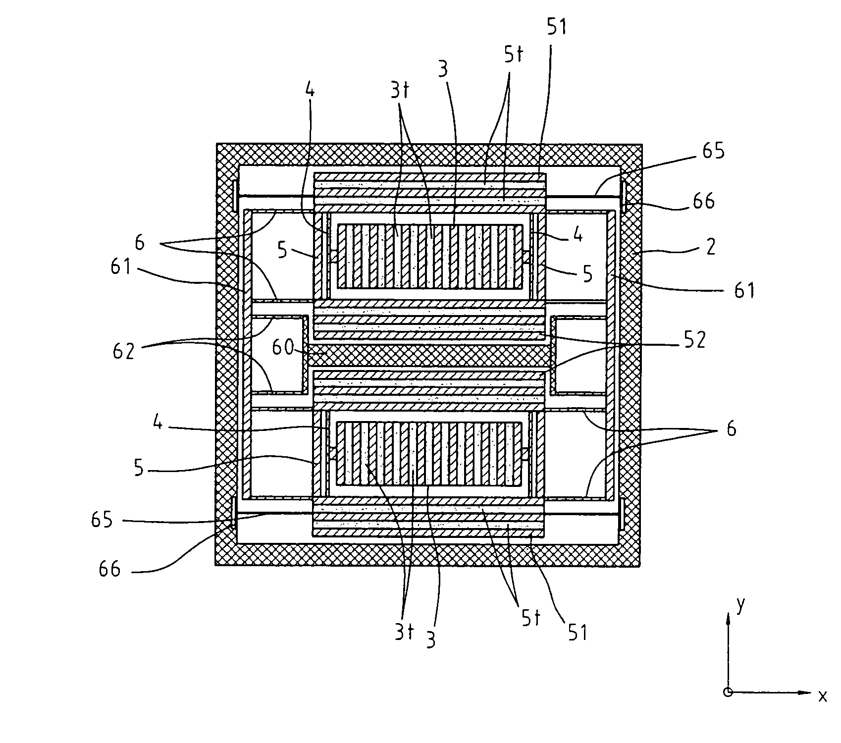
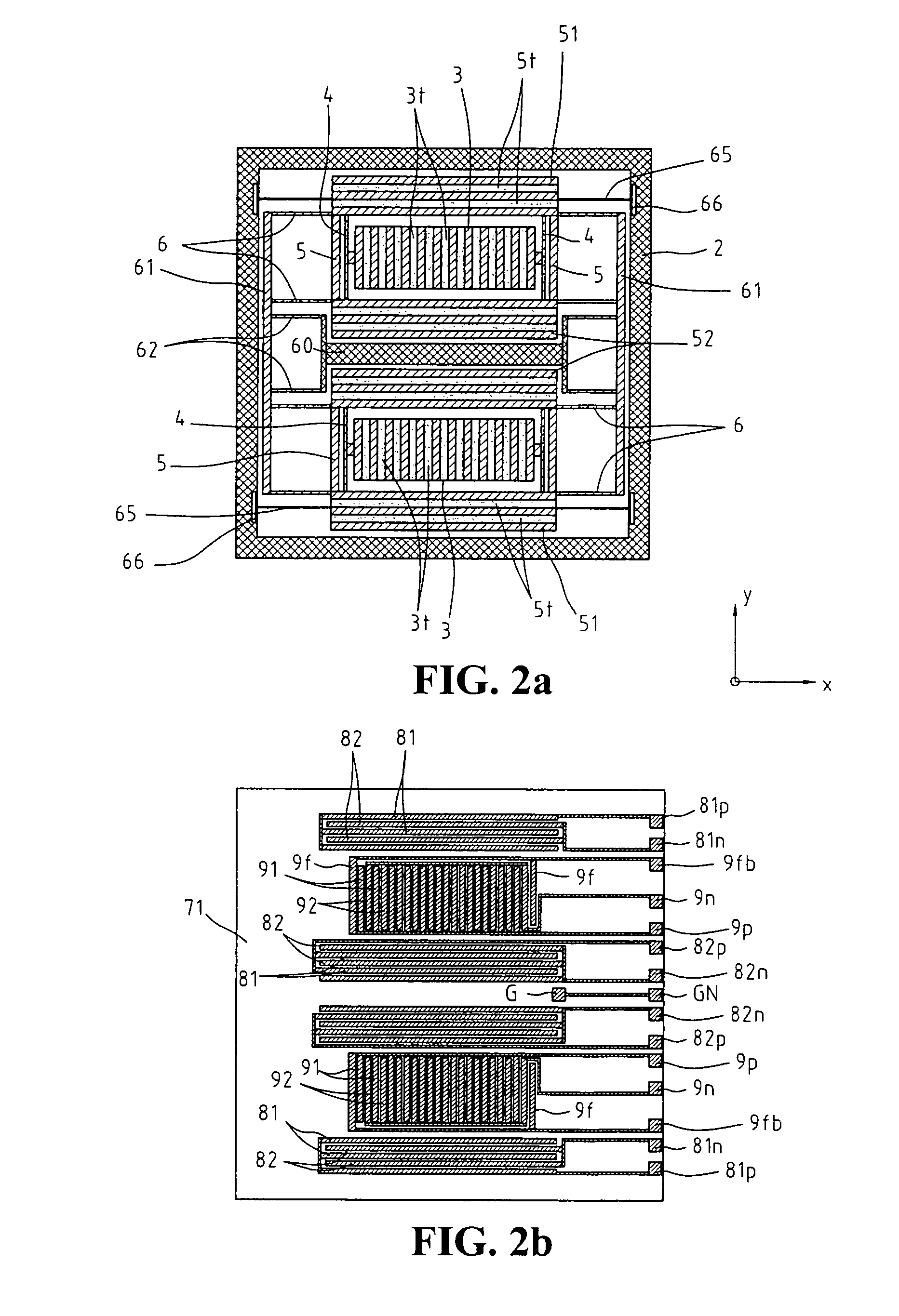
[0018] Referring to FIG. 2a, which shows a schematic view of a configuration of a z-axial solid-state gyroscope of a preferred embodiment in accordance with the present invention, the configuration is manufactured with a conductive material and comprises an outer frame 2 and a central anchor 60. The interior of the outer frame 2 has two sets of a proof mass 3 and two driver bodies 51, 52. Each proof mass 3 is respectively connected to the corresponding two driver bodies 51, 52 thereof by at least one sensing elastic beam 4. Two connection beams 5 connect the two driver bodies 51, 52 to each other. Each proof mass 3 and the corresponding driver bodies 51, 52 thereof are respectively connected to a common connection beams 61 by a number of driving elastic beams 6. The common connection beams 61 are connected to a common elastic beams 62 fixed at the central anchor 60. Each proof mass 3 and the corresponding driver bodies 51, 52 thereof are also additionally suspended to the outer fram...


PUM


Abstract

The present invention relates to a z-axial solid-state gyroscope. Its main configuration is manufactured with a conductive material and includes two sets of a proof mass and two driver bodies suspended between two plates by an elastic beam assembly. Both surfaces of the driver bodies and the proof masses respectively include a number of grooves respectively perpendicular to a first axis and a second axis. The surfaces of the driver bodies and the proof masses and the corresponding stripe electrodes of the plates thereof are respectively formed a driving capacitors and a sensing capacitors. The driving capacitor drives the proof masses to vibrate in the opposite direction along the first axis. If a z-axial angular velocity input, a Coriolis force makes the two masses vibrate in the opposite direction along the second axis. If a first axial acceleration input, a specific force makes the two masses move in the same direction along the first axis. If a second axial acceleration input, a specific force makes the two masses move in the same direction along the second axis. Both inertial forces make the sensing capacitances change. One z-axial solid-state gyroscopes and two in-plane axial gyroscopes can be designed on a single chip to form a complete three-axis inertial measurement unit.

Description

BACKGROUND OF THE INVENTION [0001] 1. Field of the Invention [0002] The present invention relates to solid-state gyroscopes and a three-axis inertial measurement unit, which are in particular manufactured by a micro-mechanical technique, and can sense three axes angular velocities and three axes accelerations simultaneously. [0003] 2. The Related Art [0004] The sensing axis of angular velocity for most of conventional gyroscopes manufactured by a micro-mechanical technique is parallel to the structure surface thereof. Furthermore, in case of needing to concurrently sense three axial angular velocities and accelerations, if the sensing axis of angular velocity is perpendicular to the structure surface thereof, the gyroscopes and accelerometers can be built on a single chip to measure three axial angular velocities and accelerations, and the cost and size thereof can be thus largely reduced. Therefore the other types of gyroscopes are born. SUMMARY OF THE INVENTION [0005]FIG. 1 shows ...

Claims


Application Information

Patent Timeline
IPC IPC(8): G01P15/08
CPCG01C19/5719G01P15/125G01P15/18G01P2015/082
Inventor CHEN, SHYU-MOUTZUOO, SHEAU-SHIKAU, CHUNG-TA
Owner MIN OF NAT DEFENSE
Why Eureka
Try Eureka