Gas setting method, gas setting apparatus, etching apparatus and substrate processing system

a technology of gas setting and etching apparatus, which is applied in the direction of fluid pressure measurement, instruments, vacuum gauges, etc., can solve the problems of difficult to properly perform the difficult to find the proper setting of each gaseous mixture and fix, and different etching characteristics at the central portion of the substrate, etc., to achieve the effect of short tim

Inactive Publication Date: 2006-07-20
TOKYO ELECTRON LTD
View PDF11 Cites 18 Cited by
  • Summary
  • Abstract
  • Description
  • Claims
  • Application Information

AI Technical Summary

Benefits of technology

[0006] The present invention is contrived on the basis of the aforementioned problems, and it is, therefore, an object of the present invention to provide a gas setting method, a gas setting apparatus, an etching apparatus and a substrate processing system, capable of readily and simply performing a setting of each gaseous mixture, which is supplied to a central portion or an outer peripheral portion of a substrate in a processing chamber, in a short time.

Problems solved by technology

However, in case where the gaseous mixture is supplied into the processing chamber through the shower head to perform the etching process on the substrate, as mentioned above, there was a problem that etching characteristics such as etching rate, etching selectivity, etching shape and the like at the central portion of the substrate are different from those at the outer peripheral portion of the substrate, respectively.
Since, however, a relationship between each etching characteristic and the mixing ratio or the flow rate of each gaseous mixture supplied to the central portion or the outer peripheral portion of the substrate was not clearly defined, it was difficult to properly perform the setting of each gaseous mixture.
Further, it takes much time to find the proper setting of each gaseous mixture and fix it.

Method used


Image

  • Gas setting method, gas setting apparatus, etching apparatus and substrate processing system
  • Gas setting method, gas setting apparatus, etching apparatus and substrate processing system
  • Gas setting method, gas setting apparatus, etching apparatus and substrate processing system

Examples


Embodiment Construction

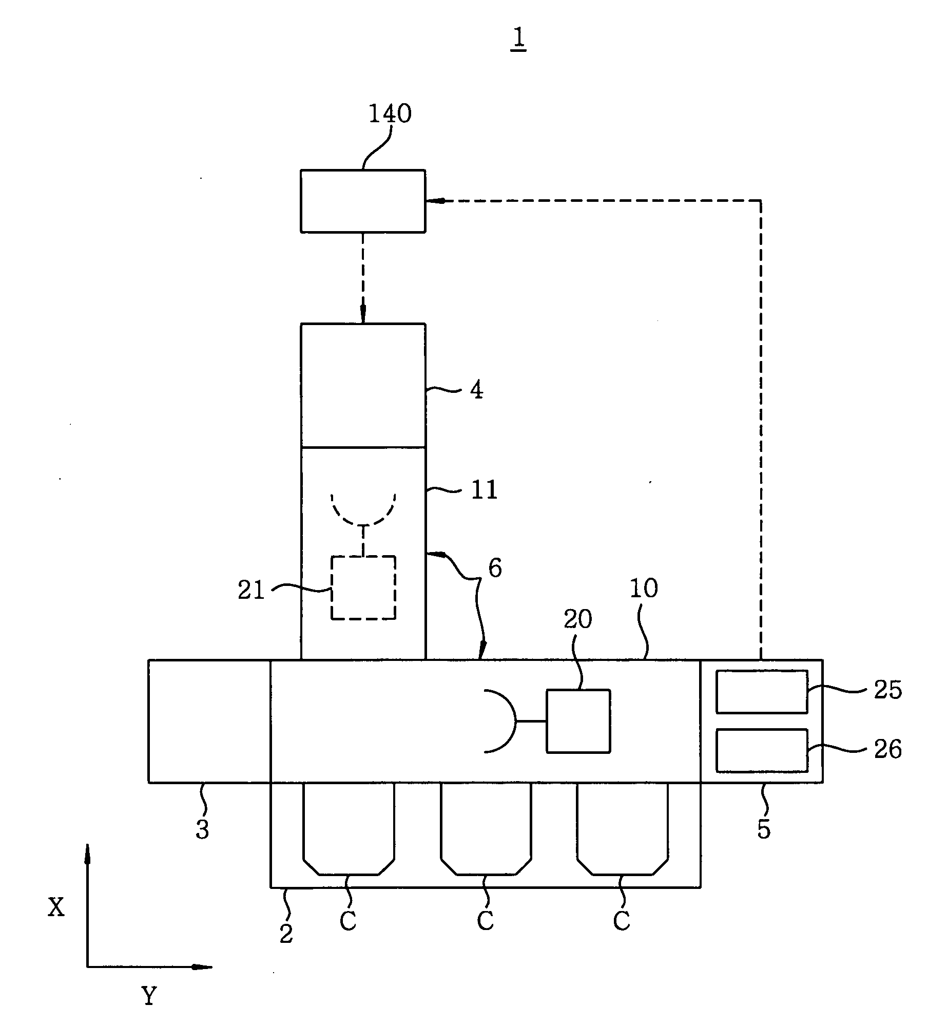
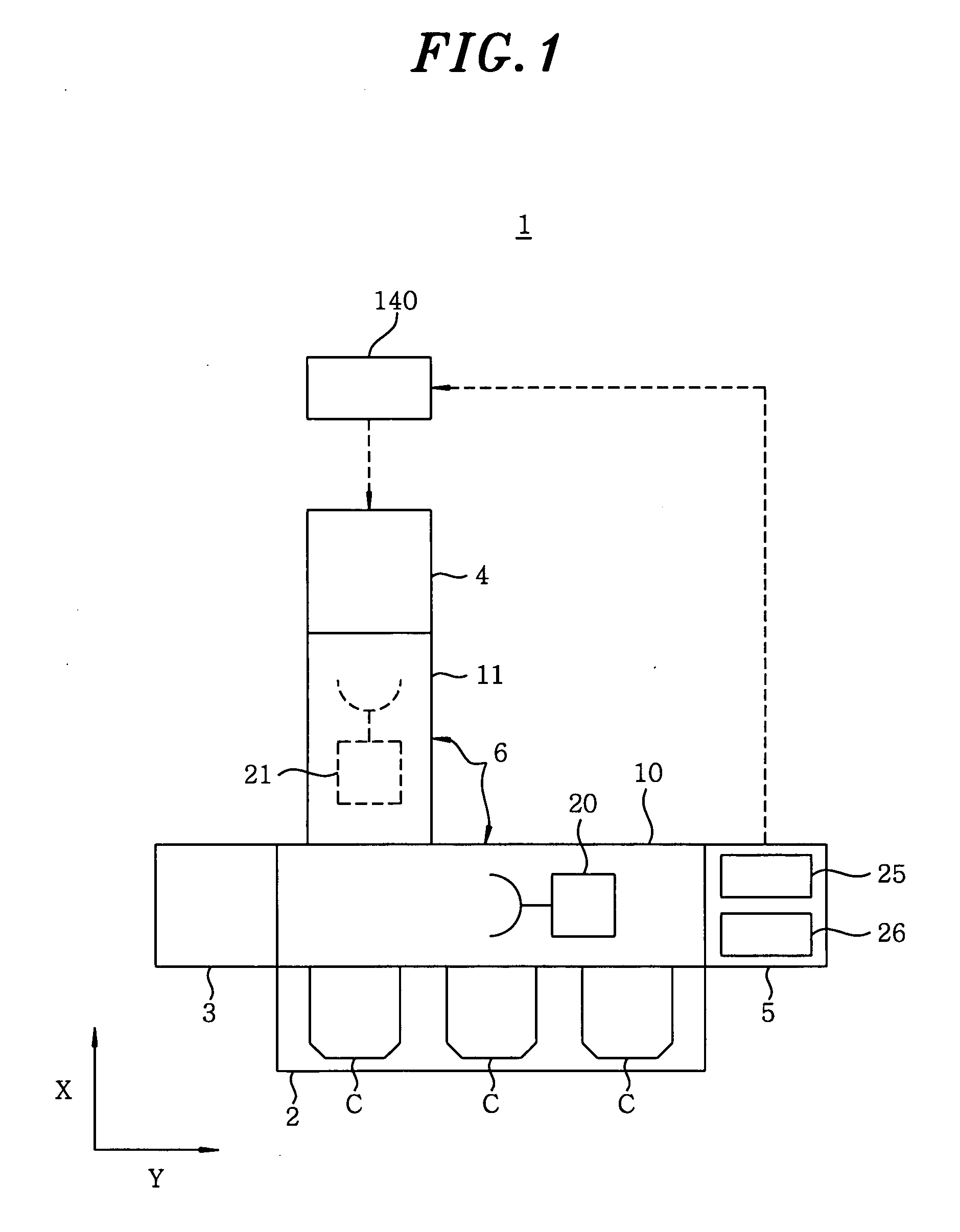
[0031] Hereinafter, preferred embodiments of the present invention will be described. FIG. 1 is a plane view showing a schematic configuration of a substrate processing system 1 having thereon an etching apparatus in accordance with the present embodiment.

[0032] The substrate processing system 1 includes a cassette mounting unit 2 for mounting thereon a plurality of cassettes C, each accommodating therein, e.g., a substrate W; an alignment unit 3 for positioning the substrate W; an etching apparatus 4 for performing an etching process on the substrate W; a measuring unit 5 for measuring an etching result of the substrate W; and a transfer unit 6 for transferring the substrate W between the cassette mounting unit 2, the alignment unit 3, the etching apparatus 4, and the measuring unit 5, wherein they are connected to each other as a unit.

[0033] The transfer unit 6 has a transfer chamber 10, to which, e.g., the cassette mounting unit 2, the measuring unit 5 and the alignment unit 3 ...


PUM

PropertyMeasurementUnit
frequencyaaaaaaaaaa
frequencyaaaaaaaaaa
frequencyaaaaaaaaaa

Abstract

Mixing ratio and flow rate of a first gaseous mixture supplied to a central portion of the substrate are set. Subsequently, etching is performed by changing a mixing ratio of a second gaseous mixture supplied to an outer peripheral portion of the substrate while a setting of the first gaseous mixture is fixed, thereby, setting the mixing ratio of the second gaseous mixture based on an etching result to make etching selectivities and shapes at the central portion and the outer peripheral portion of the substrate uniform. Then, etching is performed by changing a flow rate of the second gaseous mixture while settings of the first gaseous mixture and the mixing ratio of the second gaseous mixture are fixed, thereby, setting the flow rate of the second gaseous mixture based on etching results to make etching rates at the central portion and the outer peripheral portion of the substrate uniform.

Description

FIELD OF THE INVENTION [0001] The present invention relates to a gas setting method of an etching gas supplied to a processing chamber, a gas setting apparatus, an etching apparatus and a substrate processing system. BACKGROUND OF THE INVENTION [0002] In a manufacturing process of an electronic device such as a semiconductor device, a liquid crystal display device or the like, an etching process for etching a film on a substrate in a predetermined shape is carried out to form a predetermined circuit pattern on the substrate. [0003] In the aforementioned etching process, a plasma etching process is widely used. A plasma etching apparatus has, e.g., in a processing chamber thereof, a lower electrode for mounting a substrate thereon, and a shower head, also serving as an upper electrode, for injecting a predetermined gas toward the substrate on the lower electrode. The etching process is performed to etch a film on the substrate in such a manner that a high frequency power is applied b...

Claims


Application Information

Patent Timeline
Patent Type & Authority Applications(United States)
IPC IPC(8): B44C1/22G01R31/00C03C25/68G01L21/30
CPCH01J37/3244H01J37/32449H01L21/67069H01L21/67253
Inventor MOCHIKI, HIROMASA
Owner TOKYO ELECTRON LTD
Why Eureka
Try Eureka