Multiphase DC-DC converter

a converter and multi-phase technology, applied in the field of converters, can solve the problems of speed and function, difficult to improve load responsiveness, and increase output current, so as to increase processing speed and function, increase output current, and reduce operational voltage

Active Publication Date: 2006-07-20
CYPRESS SEMICON CORP
View PDF5 Cites 12 Cited by
  • Summary
  • Abstract
  • Description
  • Claims
  • Application Information

AI Technical Summary

Benefits of technology

[0031] Semiconductor devices such as CPUs employed in portable equipment such as portable electronic devices have not only been increasing processing speed and functions but have also been decreasing the operational voltage and increasing the output current. As a result, there has been a demand for a DC-DC converter having a lower output voltage and a higher output current. There has also been a demand for a CPU with improved responsiveness to sudden changes in the load. In order to improve the response speed of a DC-DC converter with respect to a decrease in the output voltage due to a sudden change in the load, it is preferable that the switching cycle of the output transistor be shortened.
[0036] In the fixed activation time DC-DC converter 300 of FIG. 3, the inactivation time of the output transistor T1 changes in response to changes in the output voltage Vo. Therefore, the switching frequency of the output transistor T1 substantially changes in accordance with changes in the output voltage Vo. Change in the output voltage Vo is detected by the comparator 8, which has a higher operation speed than the voltage amplifier 2 of FIG. 1 and the error amplifier 4 of FIG. 2. Thus, the fixed activation time DC-DC converter 300 has superior load responsiveness compared with the current-mode DC-DC converter 100 of FIG. 1 and the voltage-mode DC-DC converter 200 of FIG. 2.
[0037] The multiphase DC-DC converter 400 of FIG. 4 operates a load at a frequency that is substantially two times greater without increasing the switching frequency of the output transistors of the converter units 9a and 9b. This improves responsiveness with respect to a sudden change of the output voltage Vo in comparison with the current-mode DC-DC converter 100 of FIG. 1. However, the timing at which the output transistors of the converter units 9a and 9b are activated is determined by a pulse signal provided by the oscillator 5. Thus, a time lag is produced between the sudden change in the output voltage Vo and the activation of the output transistor. Therefore, the DC-DC converter 400 cannot sufficiently respond to sudden changes in the output voltage Vo.
[0038] The multiphase DC-DC converter 500 of FIG. 5 operates a load with a frequency that is two time greater without increasing the switching frequency of the output transistors of the converter units 10a and 10b. Therefore, the responsiveness to a sudden change in the output voltage Vo is further improved in comparison with the fixed activation time DC-DC converter 300 of FIG. 3.
[0039] Additionally, change in the output voltage Vo is detected by the comparator 8, which is operated at a higher speed than the voltage amplifiers 2a and 2b and the error amplifier 4 in FIG. 4. Thus, the multiphase DC-DC converter 500 has better load responsiveness than the multiphase DC-DC converter 400 of FIG. 4. However, the characteristic error of the one-shot flip-flop circuits FFa and FFb may cause a difference in activation time between the converter units 10a and 10b. Further, difference in inductance between the choke coils L1 and L2 will cause a difference between the current flowing through the choke coil L1 and the current flowing through the choke coil L2. An increase in the difference in current may lower efficiency. Furthermore, this may increase the heat generated by one of the converter units and cause a deficiency.
[0040] The present invention provides a multiphase DC-DC converter having improved responsiveness with respect to sudden changes in the output voltage while equalizing the output current of a plurality of converter units.

Problems solved by technology

Semiconductor devices such as CPUs employed in portable equipment such as portable electronic devices have not only been increasing processing speed and functions but have also been decreasing the operational voltage and increasing the output current.
Therefore, it is difficult to improve the load responsiveness by further increasing the switching frequency of the output transistor.

Method used


Image

  • Multiphase DC-DC converter
  • Multiphase DC-DC converter
  • Multiphase DC-DC converter

Examples


Embodiment Construction

[0054] In the drawings, like numerals are used for like elements throughout.

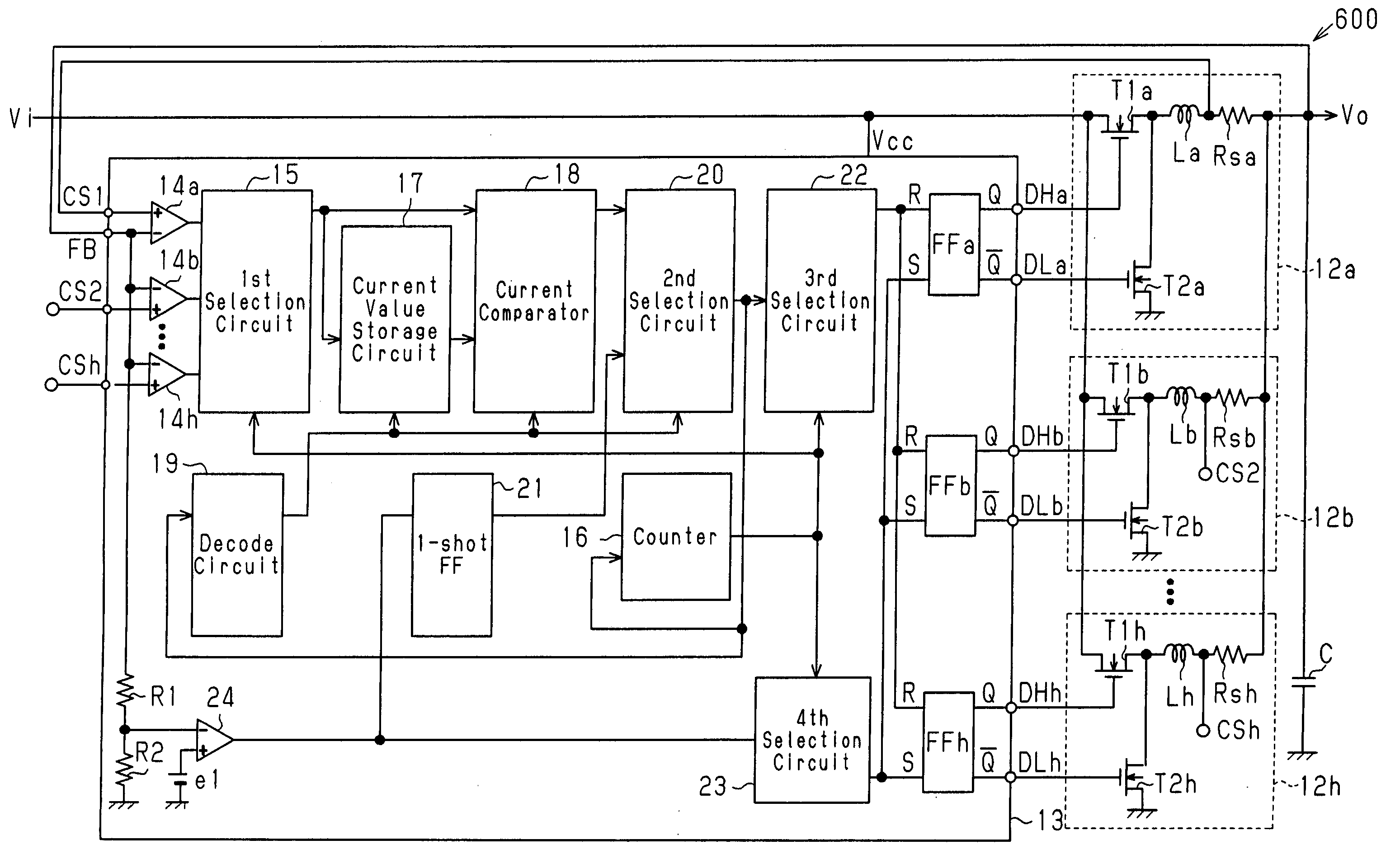
[0055]FIG. 6 is a schematic block circuit diagram showing a multiphase DC-DC converter 600 according to a first embodiment of the present invention. The first embodiment is an eight-phase multiphase DC-DC converter. The multiphase DC-DC converter 600 includes eight converter units 12a to 12h, and a control unit 13 for controlling the converter units 12a to 12h. The multiphase DC-DC converter 600 is operable in both the current mode and fixed activation time mode.

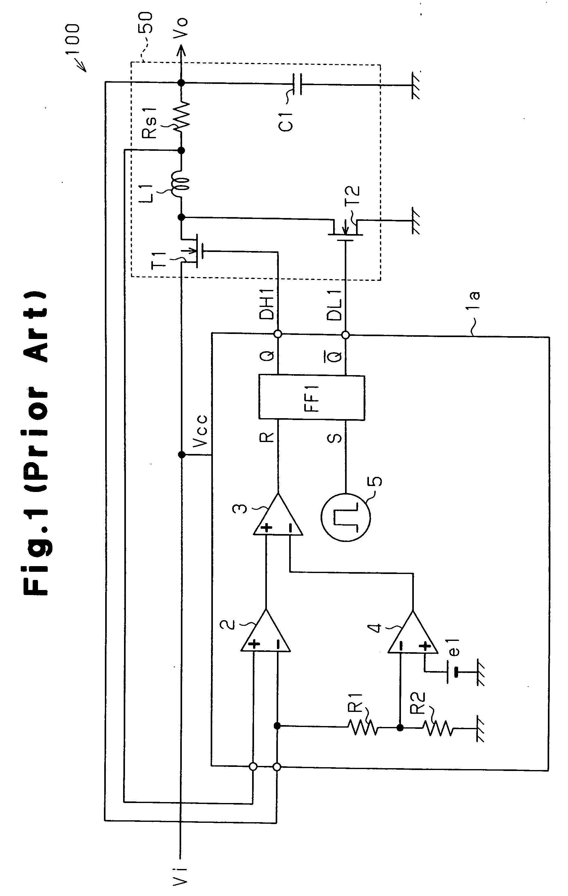
[0056] The converter units 12a to 12h have the same structure as the converter unit 50 of the current-mode DC-DC converter 100 in FIG. 1. The converter units 12a to 12h include output transistors T1a to T1h, synchronous rectifying transistors T2a to T2h, choke coils La to Lh, and current detection resistors Rsa to Rsh, respectively. The converter units 12a to 12h share a smoothing capacitor C.

[0057] The control unit 13 includes eight voltage ampli...


PUM


Abstract

A multiphase DC-DC converter that equalizes the output current of a plurality of converter units while improving responsiveness with respect to sudden changes in the output voltage. The converter includes a control unit for controlling the converter units. The control unit includes a comparator for comparing the output voltage of each of the converter units with a reference voltage, a first control circuit for sequentially selecting each of the converter units in accordance with an output signal of the comparator to activate the output transistor of the selected converter unit, and a second control circuit for controlling the inactivation timing of the output transistors of the converter units so as to equalize the output current of the converter units.

Description

CROSS-REFERENCE TO RELATED APPLICATIONS [0001] This application is based upon and claims the benefit of priority from the prior Japanese Patent Application No. 2005-012045, filed on Jan. 19, 2005, the entire contents of which are incorporated herein by reference. BACKGROUND OF THE INVENTION [0002] The present invention relates to a converter, and more particularly, to a multiphase DC-DC converter. [0003]FIG. 1 is a schematic block circuit diagram of a current-mode DC-DC converter 100. The converter 100 includes a control unit 1a and a converter unit 50. The converter unit 50 includes an output transistor T1 formed by an N-channel MOS transistor, a synchronous rectifying transistor T2 formed by an N-channel MOS transistor, a choke coil L1, a current detection resistor Rs1, and a smoothing capacitor C1. [0004] The control unit 1a generates output signals DH1 and DL1, which are complementary signals, and provides the output signal DH1 to the gate of the output transistor T1 and the out...

Claims


Application Information

Patent Timeline
Patent Type & Authority Applications(United States)
IPC IPC(8): G05F1/656G05F1/10
CPCH02M3/1584
Inventor NISHIMORI, EIJI
Owner CYPRESS SEMICON CORP
Why Eureka
Try Eureka