Automotive radar

a technology for autos and radars, applied in the field of autos, can solve the problems of unsuitable for widening the detection range, and entail increasing the size and cost of beams, so as to increase the signal processing load for detection, widen the overall detection range, and reduce the effect of beam siz

Inactive Publication Date: 2006-07-20
HITACHI LTD
View PDF8 Cites 54 Cited by
  • Summary
  • Abstract
  • Description
  • Claims
  • Application Information

AI Technical Summary

Benefits of technology

[0005] As one approach to a wider detection range, the monopulse method employs a plurality of receiving antennas and determines the direction of a target object such as an obstacle (hereinafter referred to as a “target”) according to amplitude or phase difference between received signals. For example, as shown in FIG. 14, reflected waves 33 from a target vehicle 19 are received by two receiving antennas 34 and a sum signal 36 and a differential signal 37 are first generated in a hybrid circuit 35. FIG. 15 shows the azimuthal characteristic 38 of the sum signal and the azimuthal characteristic 39 of the differential signal; and FIG. 16 shows the azimuthal characteristic 40 as the ratio of sum signal to differential signal. In FIG. 16, the ratio of sum signal to differential signal is expressed by a monotonically decreasing function of azimuth, so that the azimuth can be uniquely determined based on the ratio of sum signal to differential signal, 40. Within an azimuth range in which a target can be identified, a plurality of targets scattered over a wide area can be detected accurately at the same time, leading to an excellent system response.
[0014] In the mechanical scanning method as described in the Japanese Patent Laid-open No. 2000-22423, the primary radiator is movable with respect to the focal plane as mentioned above and scanning is made with a single relatively narrow beam as used in the monopulse method, which broadens the overall detection range and eliminates the need for a larger system. However, the beam shape changes with direction and an adjustment is necessary for each scan. Besides, since scanning is continuously made, the use of a reflected signal in the course of scanning for detection is unavoidable. Therefore, this means the need for continuous adjustments. As a consequence, the signal processing load for detection increases and the signal processing speed decreases, which might result in failure to achieve the system response indispensable for wide-angle detection.
[0015] A system which uses a monopulse type antenna for each direction and provides a wider detection range by switching these antennas was considered prior to the present invention. In this system, the beam shape does not change with direction and a stationary antenna is used for detection, which means that the signal processing load is not so significant as mentioned above and the signal processing speed is higher. As compared with the above beam switch method where direction cannot be identified by a single beam, the system based on monopulse type beams enables direction identification within the detection range and thus the required number of antennas is remarkably decreased. Nevertheless, plural antennas are needed and increase in overall size is inevitable.

Problems solved by technology

The beam switch method has a problem that the use of a larger number of beams entails increase in size and cost and therefore is unsuitable as a means to widen the detection range.

Method used


Image

  • Automotive radar
  • Automotive radar
  • Automotive radar

Examples


first embodiment

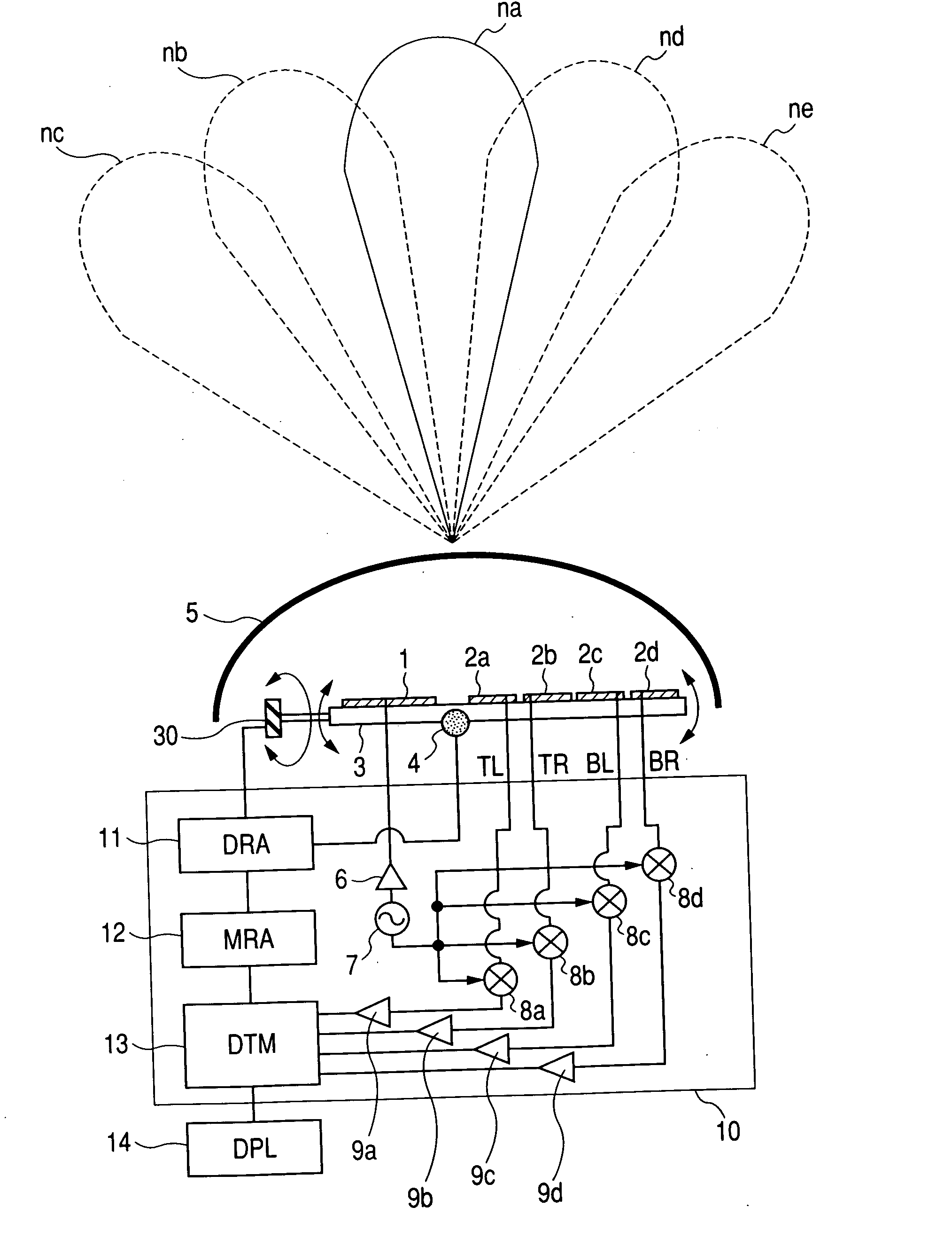
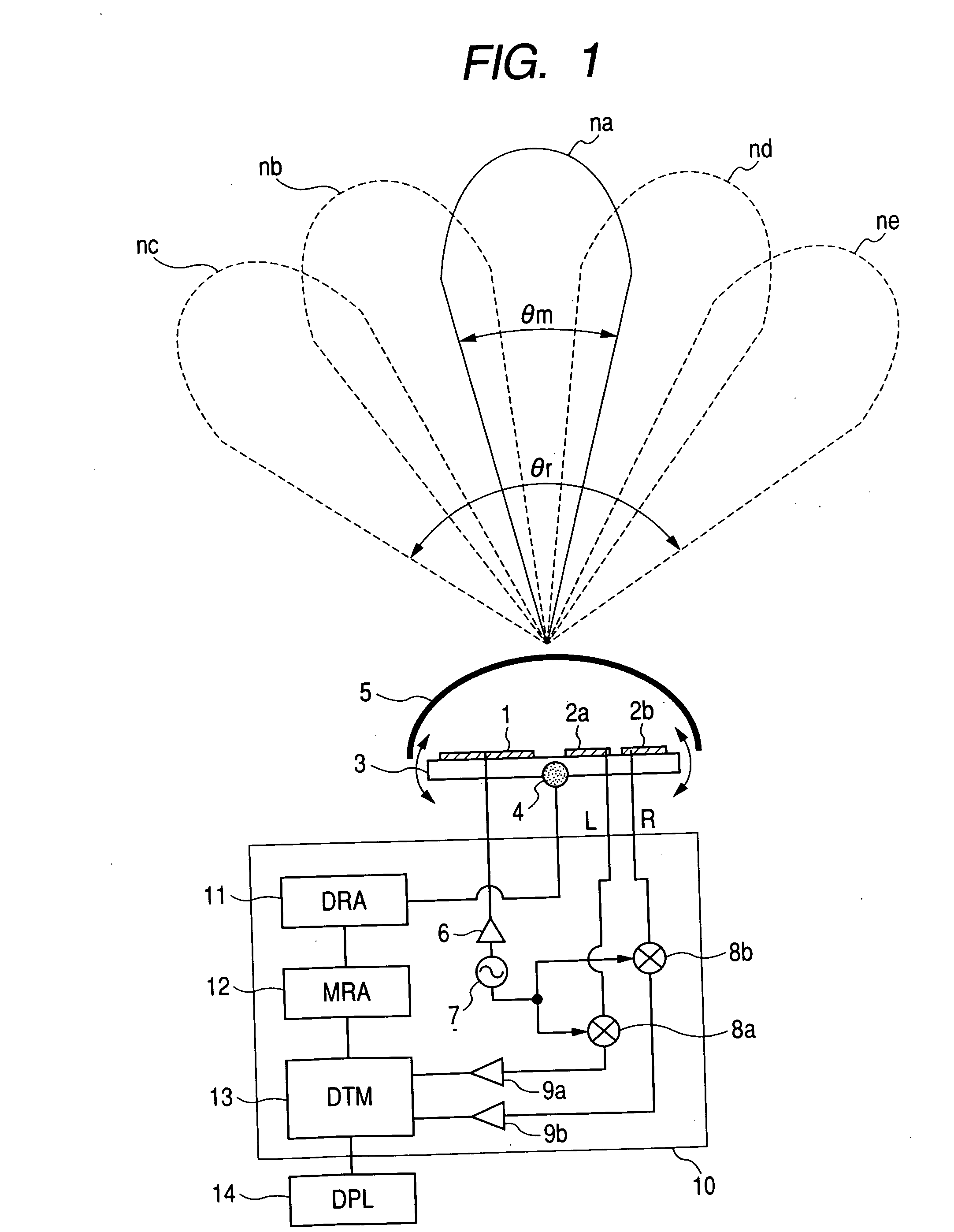
[0040]FIG. 1 is a block diagram showing the present invention. A transmitting array antenna (transmitting antenna) 1 and receiving array antennas (receiving antennas) 2a and 2b are arranged on an antenna plate 3. A millimeter-wave signal generated by an oscillator 7 is sent through a power amplifier 6 to the transmitting array antenna 1. A transmitted signal as an electromagnetic wave from the transmitting array antenna 1 is reflected by a target (not shown) and the reflected signal is received by the receiving array antennas 2a and 2b, which then outputs received signals L and R. The received signals L and R enter mixers 8a and 8b respectively where they are mixed with an output signal from the oscillator 7 and converted into intermediate frequency signals. The intermediate frequency signals are amplified by low-noise amplifiers 9a and 9b before entering a signal processing circuit (DTM) 13.

[0041] An azimuth motor 4 rotates the antenna plate 3 in the azimuth direction with the azim...

third embodiment

[0071] As in the third embodiment, the automotive radar in this embodiment performs wide-angle detection by scanning a narrow detection angle. This excludes signals beyond the detection angle range. For example, right and left roadside objects can be isolated from a target on the road in terms of time. In this case, because one antenna unit incorporating transmitting and receiving antennas is rotated, the beam shape does not change with direction; in addition, there is rest time in the course of scanning, and signal processing is performed during the rest time, so that no adjustment is needed in signal processing. Therefore, high speed signal processing can be performed to detect a target in a wide angle range. In addition, since only one antenna unit incorporating a set of transmitting and receiving antennas is used as mentioned above, the system need not be large. Here, scanning is made on an antenna detection angle for identifying the direction of a target in accordance with the ...


PUM


Abstract

An automotive radar which can process signals at high speed to detect a target in a wide angle range is provided. The automotive radar comprises a transmitting antenna which emits an electromagnetic wave, two receiving antennas which receive the electromagnetic wave reflected by a target, an antenna plate on which the transmitting antenna and two receiving antennas are arranged. It also includes a drive which rotates the antenna plate in an azimuth direction, which corresponds to the direction of arrangement of the two receiving antennas, to scan a detection angle formed by the two receiving antennas. The drive has rest time between scans to stop rotation. The automotive radar also includes a signal processor which detects the azimuth angle of the target with respect to a reference direction during the rest time according to received signals from the two receiving antennas and the rotation angle of the antenna plate at rest.

Description

CLAIM OF PRIORITY [0001] The present patent application claims priority from Japanese application JP 2005-012460 filed on Jan. 20, 2005, the content of which is hereby incorporated by reference into this application. FIELD OF THE INVENTION [0002] The present invention relates to an automotive radar which is intended to be mounted in a mobile body such as a vehicle to detect the direction of a target object such as an obstacle and its distance and velocity relative to the mobile body. BACKGROUND OF THE INVENTION [0003] As an approach to a wide angle millimeter-wave radar, an article in the Proceedings of the 2001 IEICE General Conference (Engineering Sciences), (Japan), Article No. A-17-10, p. 391, discusses that the monopulse method is used to decrease the number of antenna elements intentionally to provide a wider angle detection range for the purpose of direction detection. The monopulse method employs a plurality of receiving antennas and determines the direction of an obstacle a...

Claims


Application Information

Patent Timeline
Patent Type & Authority Applications(United States)
IPC IPC(8): G01S13/42G01S13/44G01S13/931H01Q21/06
CPCG01S7/2925G01S13/449G01S13/52G01S13/931H01Q3/06H01Q3/08H01Q25/02G01S2013/468G01S2013/9353G01S2013/9375G01S2013/9378G01S2013/9385G01S2013/9321G01S2013/93274G01S2013/93272G01S2013/932G01S2013/93271
Inventor SHINODA, HIROSHINAGASAKU, TOSHIYUKIKONDOH, HIROSHI
Owner HITACHI LTD
Why Eureka
Try Eureka