Authentication system

a communication system and authentication technology, applied in the field of communication systems, can solve the problems of physical inability to communicate in the direction other than the forward direction of the human chest, physical inability to communicate, and low degree of freedom of communication

Inactive Publication Date: 2006-07-20
SONY CORP
View PDF7 Cites 66 Cited by
  • Summary
  • Abstract
  • Description
  • Claims
  • Application Information

AI Technical Summary

Benefits of technology

[0024] Consequently, the authentication system is able to realize sending and receiving of information without directional restrictions in the neighborhood of the user, with confidentiality secured, and without forcing the user to perform a predetermined movement, and it is also able to identify even the relation between the device and the human body based on information specific to the human body.

Problems solved by technology

Furthermore, since the action of a capacitor using a human body intervening between sending and receiving electrodes as a medium is the premise of physical action, it is physically impossible, when the sending electrode is fitted to the human's right wrist, for example, to communicate in directions other than the direction from the human's right wrist to the fingertip.
When the sending electrode is fitted near the human's chest, communication in directions other than the forward direction from the human's chest is physically impossible.
As described above, in communication systems, since the action of a capacitor using a human body intervening between sending and receiving electrodes as a medium is the premise of physical action, there have been a problem that the communication direction is restricted by the position of the electrode fitted to a human body as well as a problem that the degree of freedom in communication is low because the communication strength depends on the electrode area.

Method used


Image

  • Authentication system
  • Authentication system
  • Authentication system

Examples


Embodiment Construction

[0049] The present invention is now described in detail with reference to the drawings.

(1) Summary of the Invention

[0050] According to the invention, information is sent and received using an electric field. The summary of the present invention is now described in terms of the relation with the electric field.

(1-1) Electric Field

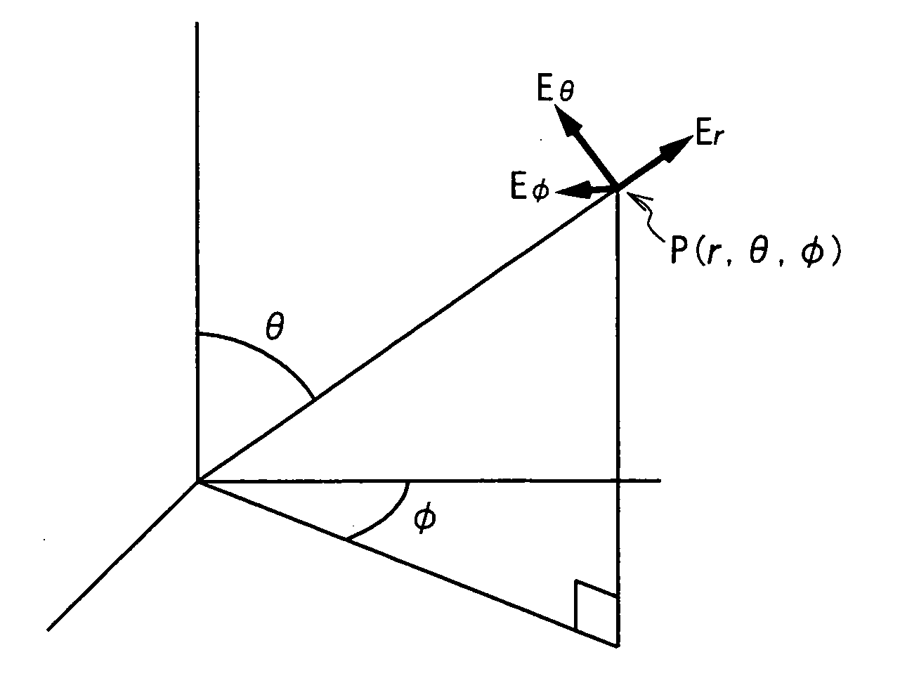
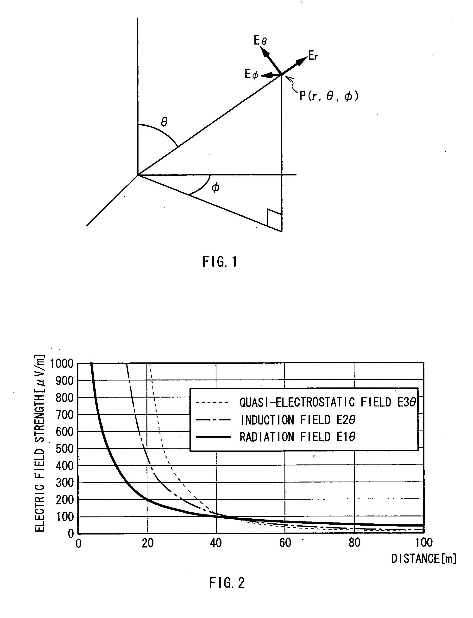
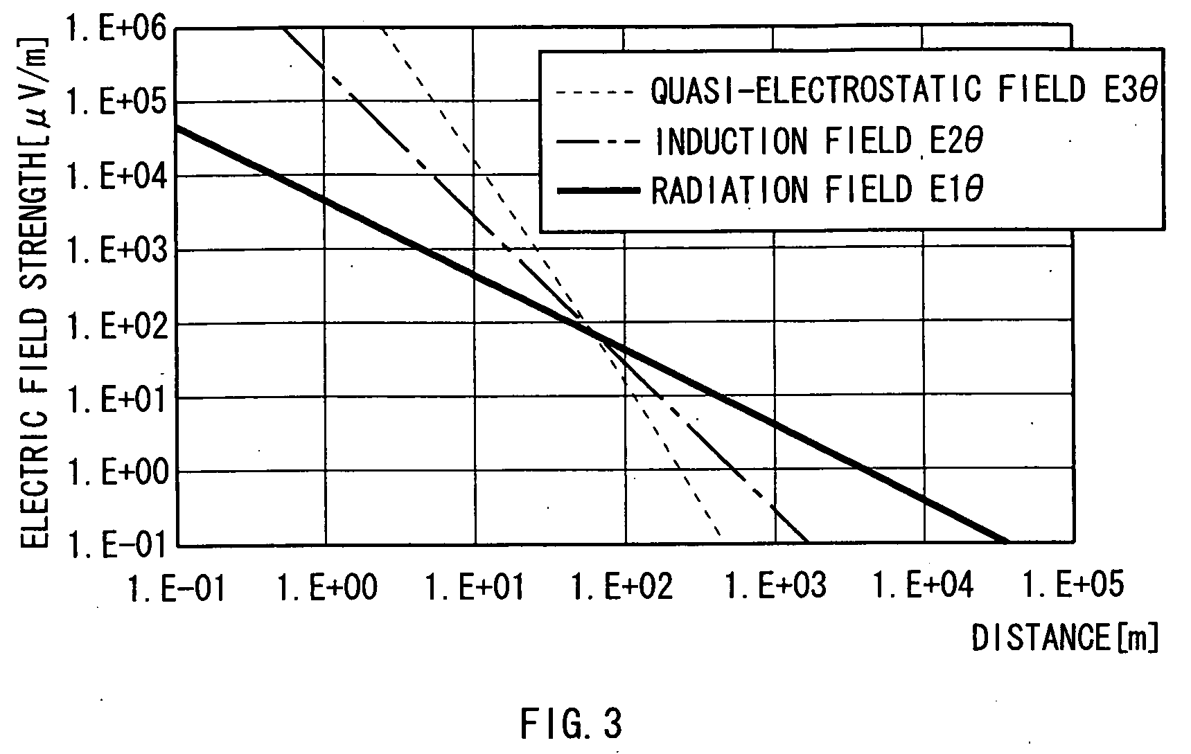
[0051] Generally, when current flows through an electric dipole (dipole antenna), the electric field E generated according to the distance r from the antenna can be represented in a simplified formula as shown below: E0=A⁡(1r3+jkr2+k2r1)(1)

where j is an imaginary unit, A is a constant, and k is the number of waves.

[0052] As shown in the above formula (1), the electric field E can be roughly separated into a component which is in inverse proportion to the distance r raised to the third power (hereinafter, this component is referred to as a quasi-electrostatic field), a component which is in inverse proportion to the distance r raised to the second po...


PUM


Abstract

The present invention enables the degree of freedom in communication to be enhanced. According to the present invention, in an authentication system 1, during a walking motion of a user which is essentially required for the user to pass through an entrance/exit passage portion 4 (FIG. 6), tissue information D5 and walking information D7 as living organism identification information, a pattern specific to a user, is detected from an detection electrode 52 via an FET 11, based on a walking quasi-electrostatic field HSE formed in the neighborhood of the user. Thereby, information with high identifiability specific to the user can be obtained without controlling movements of the user and without performing special processing such as encryption. Thus, the degree of freedom in communication can be enhanced.

Description

TECHNICAL FIELD [0001] The present invention relates to a communication system and is preferably applicable to a communication system for sending and receiving information via an electric field, for example. BACKGROUND ART [0002] Conventionally, communication systems have been adapted to send and receive information using a radiation field (radio waves), for example, between mobile telephones, and send and receive information via electromagnetic induction, for example, between the coil in a data reader / writer provided on a ticket checking and collecting machine at a station and the coil in an IC card. [0003] Recently, there have been proposed communication systems which are provided with a human-body-side communication device fitted in contact with the skin of a human body and an equipment-side communication device in the neighborhood of the user as shown in Table 1 below. In these communication systems, an alternating voltage is applied to the human body via the electrode of the hu...

Claims


Application Information

Patent Timeline
Patent Type & Authority Applications(United States)
IPC IPC(8): H01T23/00A61B5/04E05B49/00A61B5/0488A61B5/117G07C9/00H04L9/32
CPCG07C9/00087G07C9/00111H04B13/005G07C9/257G07C9/28A61B5/117
Inventor TAKIGUCHI, KIYOAKI
Owner SONY CORP
Why Eureka
Try Eureka