Pulsed laser light source

a laser light source and pulse technology, applied in lasers, laser details, electrical equipment, etc., can solve the problems of relatively large peak power, low repetition rate, and inability to directly adjust the pulsewidth

Inactive Publication Date: 2006-07-20
INSTITUT NATIONAL D'OPTIQUE
View PDF14 Cites 60 Cited by
  • Summary
  • Abstract
  • Description
  • Claims
  • Application Information

AI Technical Summary

Benefits of technology

[0011] The pulsed laser light source further comprises a pulse shaping stage optically coupled to the pulse generation stage for receiving the pulsed light beam therefrom, the pulse shaping stage including a second modulator for temporally modulating the pulsed light beam in at least a partial synchronization with the first modulator so as further determine the pulse shape of the optical pulses. The pulse shaping stage further includes a second gain medium downstream the second modulator for further amplifying the pulsed light beam.

Problems solved by technology

The resulting peak power is fairly large, but the spectrum is often composed of several longitudinal modes and the repetition rate is generally low due to the limited repetition frequency of the switching device.
Moreover, the pulsewidth is not directly adjustable, and it varies with the pumping rate, the repetition rate and the cavity optical length.
Another drawback is a “jitter” of the output beam, that is, substantial variations of the delay between the moment when the pulse is triggered and the launching of the laser output pulse.
Directly pulsing the laser diode current can however generate transient effects that can affect both the spectrum and the noise figure of the seed source.
Furthermore, longitudinal mode beating can be an important source of high frequency noise which consequently gives rise to peak power fluctuations in the pulse structure.
Depending on its amplitude and frequency spectrum, this noise can severely limit one's ability to generate stable optical pulses having special shapes with fine structures.
A drawback of the self-seeded source of LAROSE et al. is that the obtained pulse shape includes a step or “pedestal” preceding the desired pulse associated with residual ASE when the second gain medium is used.
A second drawback of the self-seeded source of LAROSE et al. is that the modulator extinction ratio must be high in order to prevent spurious lasing of the source due to the parasitic back reflections coming from the output isolator or from other components such as the pump couplers.
This ultimately limits the maximum achievable output power of the source and its stability, depending on both the modulator extinction ratio and the back reflection level of the other optical components.

Method used


Image

  • Pulsed laser light source
  • Pulsed laser light source
  • Pulsed laser light source

Examples


Embodiment Construction

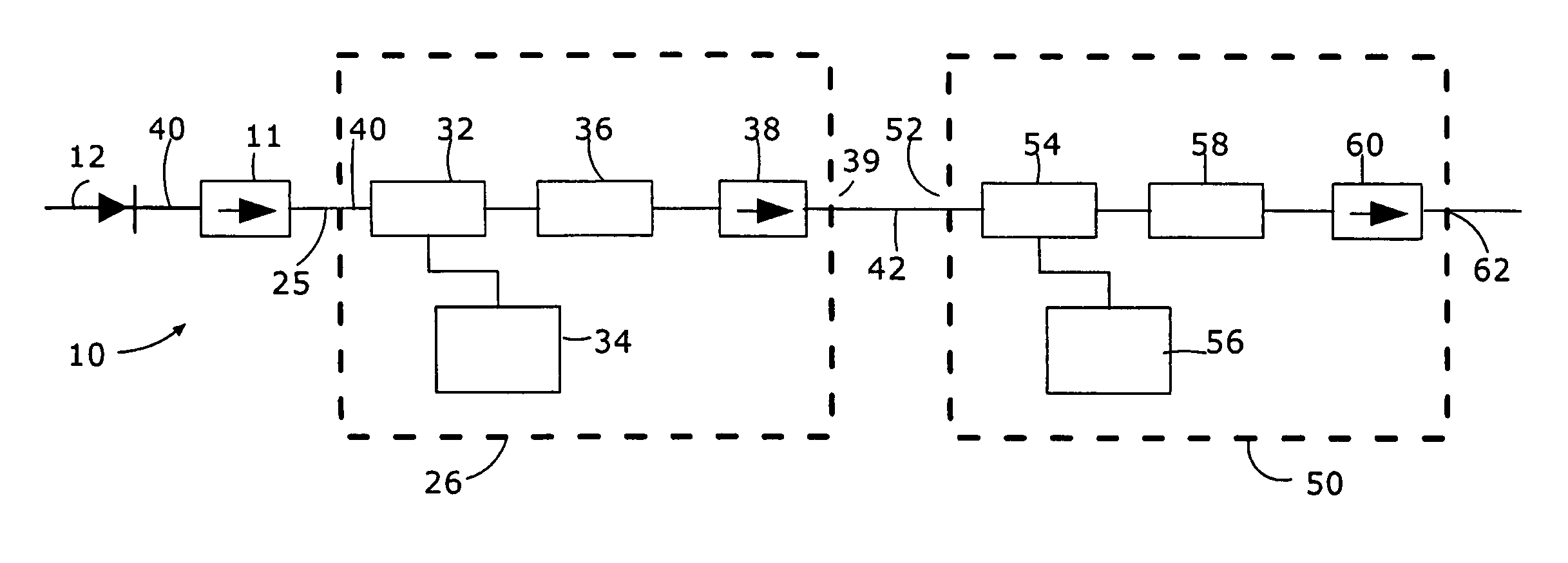
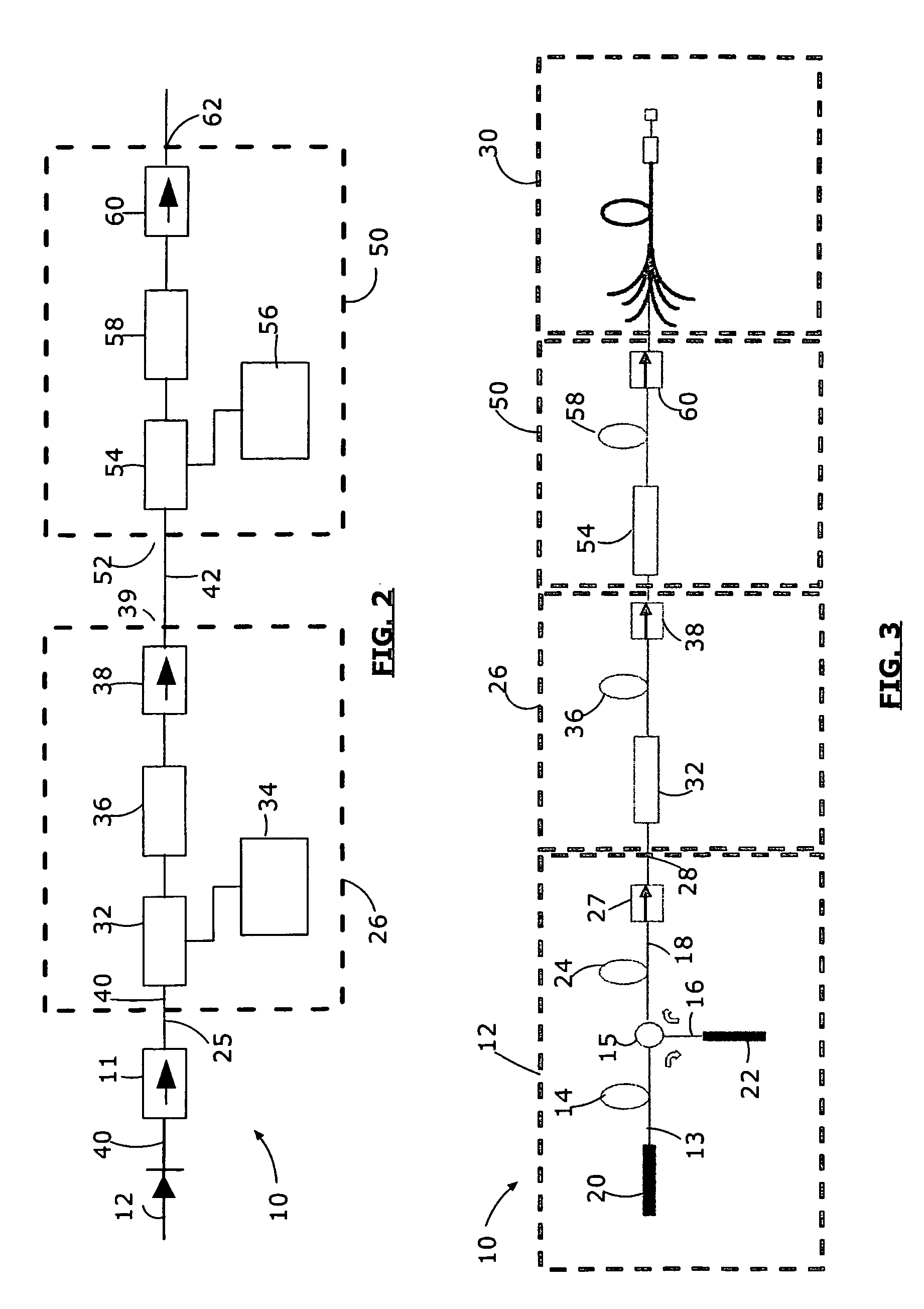
[0017] Referring to FIG. 2, there is shown a pulsed laser light source according to a preferred embodiment of the invention.

[0018] The pulsed laser source 10 first includes a continuous wave (CW) light source 12 generating a continuous light beam 40. In the embodiment of FIG. 2, the CW light source is a laser diode, but any other light source generating an appropriate continuous beam could be considered, such as for example a superfluorescent source (see description of FIG. 3 below), a CW fiber laser or a fiber coupled CW bulk solid-state laser source. The continuous light beam 40 preferably has a spectral shape which will determine the spectral shape of the light outputted by the entire pulsed light source 10. Advantageously, the laser diode may be selected or replaced depending on the required spectral profile of the outputted light. Alternatively, a wavelength tunable source may be used. Additional components may optionally be provided downstream the laser diode to modify its sp...


PUM


Abstract

A pulsed laser light source is provided. A continuous light beam is first generated by a CW laser source such as a laser diode, a superfluorescent source or a CW solid state laser. The continuous light beam is then modulated by a first modulator, and further shaped by a second modulator at least in partial synchronization with the first. The first and second modulators are preferably each followed by a gain medium for signal amplification.

Description

FIELD OF THE INVENTION [0001] The present invention relates to the field of laser light sources and more particularly concerns a pulsed laser source which provides optical output pulses with temporal shape flexibility. BACKGROUND OF THE INVENTION [0002] Pulsed laser sources are currently of considerable interest in a variety of fields such as material processing, range finding, remote detection or communication-related applications. It is usually desirable to produce a high peak power from a pulsed laser. Three main techniques are generally used for that purpose: Q-switching, mode-locking, and gated cascade amplification. [0003] The Q-switching method consists of switching from a high-loss to a low-loss condition in a laser cavity. A Q-switched laser system typically comprises a gain medium, pumped by laser diodes or other external pumping source, and a mirror on each side thereof to generate the laser oscillation. The switching between a high-loss and low-loss condition is generall...

Claims


Application Information

Patent Timeline
Patent Type & Authority Applications(United States)
IPC IPC(8): H01S3/10H01S3/13
CPCH01S3/0064H01S3/0085H01S3/06758H01S3/10015H01S2301/02
Inventor DELADURANTAYE, PASCALTAILLON, YVESLAROSE, ROBERT
Owner INSTITUT NATIONAL D'OPTIQUE
Why Eureka
Try Eureka