Contactless connector systems

a technology of contactless connectors and connectors, applied in the direction of transmission, instruments, sustainable buildings, etc., can solve the problem that the uwb communications system is relatively unsusceptible to multipath effects, and achieve the effect of facilitating high resolution position determination and measurement, and reducing the probability of interceptions

Inactive Publication Date: 2006-07-20
ARTIMI
View PDF10 Cites 144 Cited by
  • Summary
  • Abstract
  • Description
  • Claims
  • Application Information

AI Technical Summary

Benefits of technology

[0007] UWB communications systems have a number of characteristics that can make then more desirable than conventional systems. Broadly speaking, the very large bandwidth facilitates very high data rate communications and since pulses of radiation are employed the average transmit power (and also power consumption) may be kept low even though the power in each pulse may be relatively large. Also, since the power in each pulse is spread over a large bandwidth, the power per unit frequency may be very low indeed, allowing UWB systems to coexist with other spectrum users and, in military applications, providing a low probability of intercept. The short pulses also make UWB communications systems relatively unsusceptible to multipath effects since multiple reflections can in general be resolved. The use of short pulses also facilitates high resolution position determination and measurement in both radar and communication systems. Finally UWB systems lend themselves to a substantially all-digital implementation, with consequent cost savings.

Problems solved by technology

The short pulses also make UWB communications systems relatively unsusceptible to multipath effects since multiple reflections can in general be resolved.

Method used


Image

  • Contactless connector systems
  • Contactless connector systems
  • Contactless connector systems

Examples


Embodiment Construction

[0022] While specific configurations and arrangements are discussed, it should be understood that this is done for illustrative purposes only. A person skilled in the pertinent art will recognize that other configurations and arrangements can be used without departing from the spirit and scope of the present invention. It will be apparent to a person skilled in the pertinent art that this invention can also be employed in a variety of other applications.

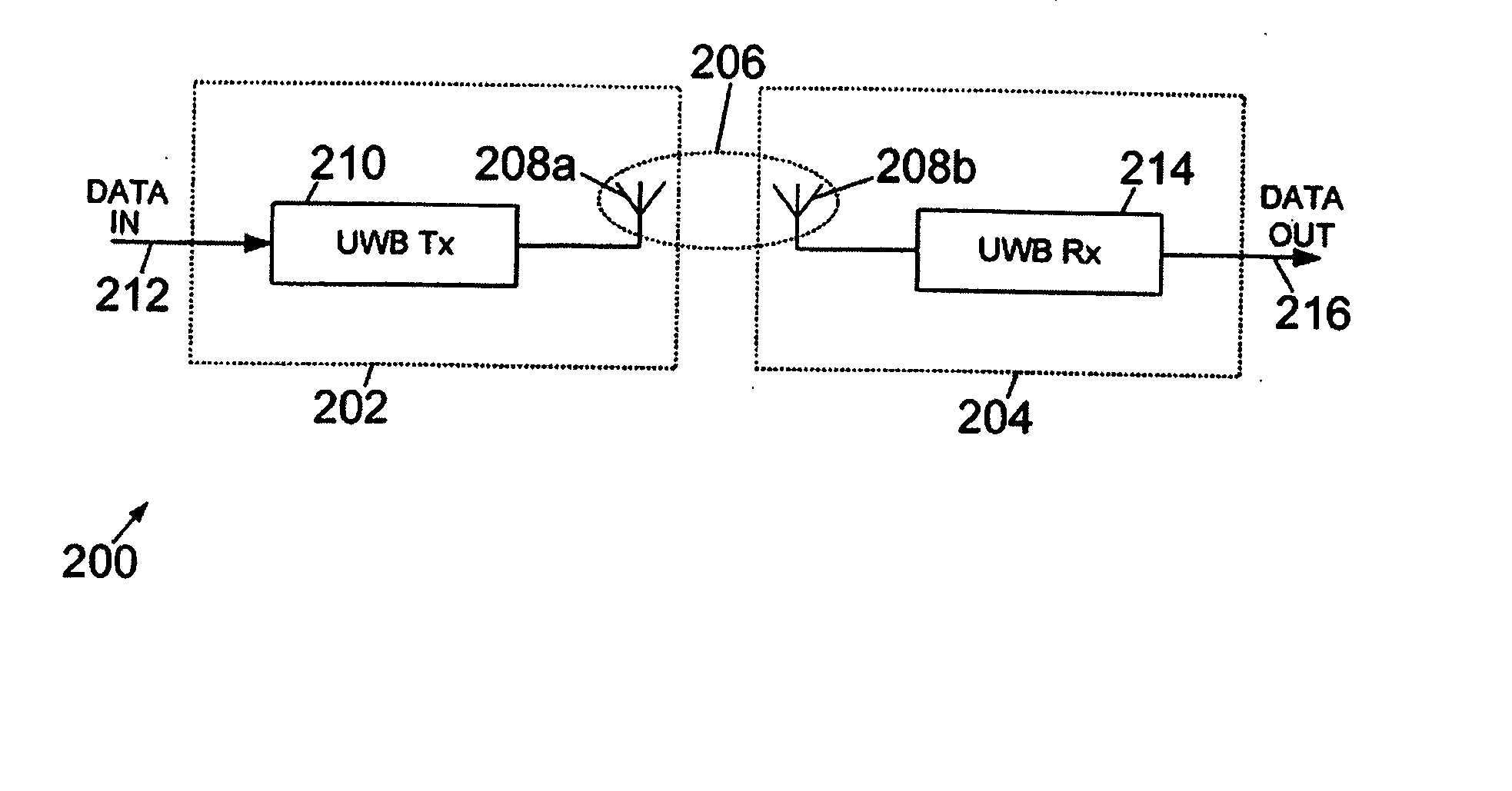
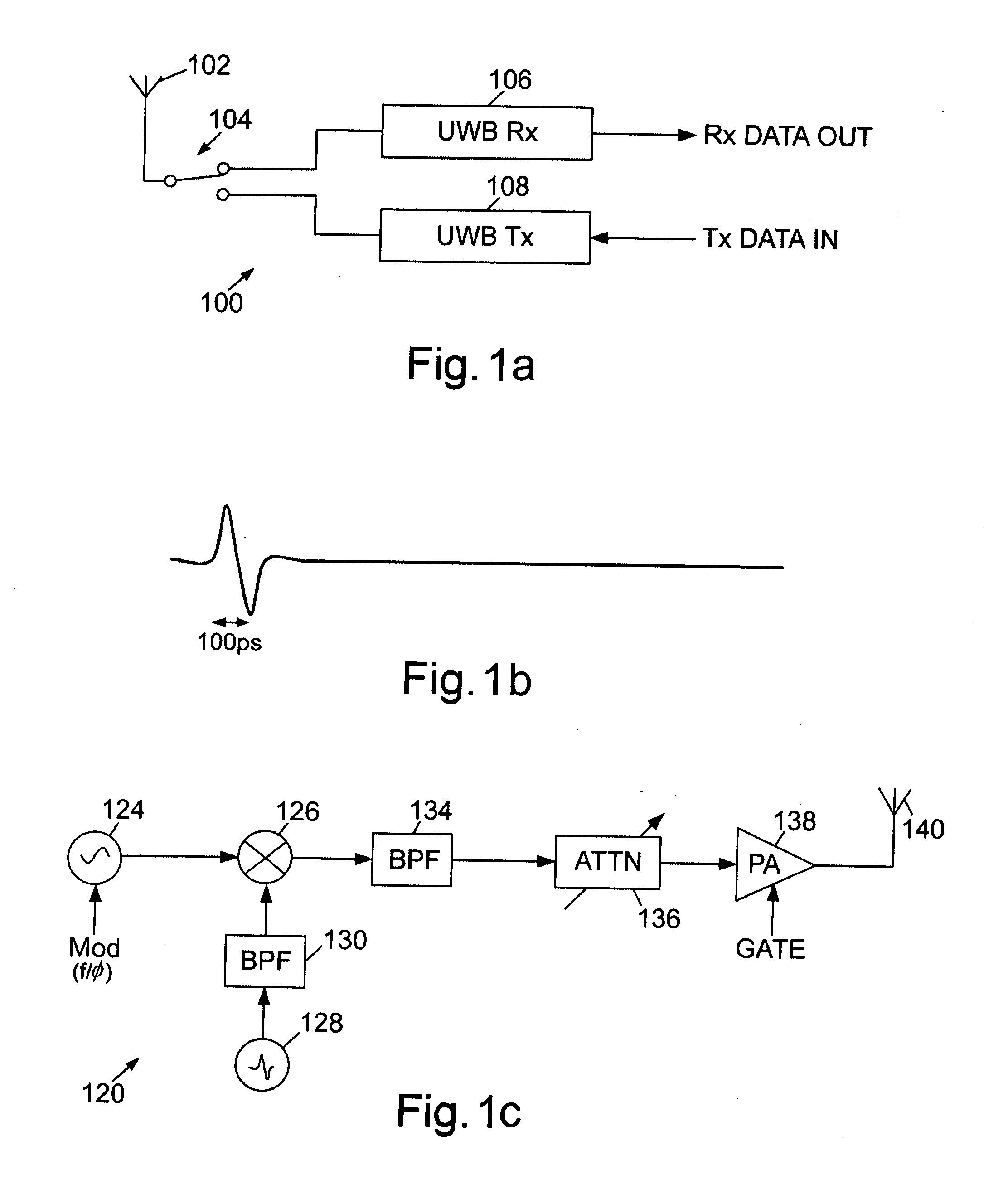
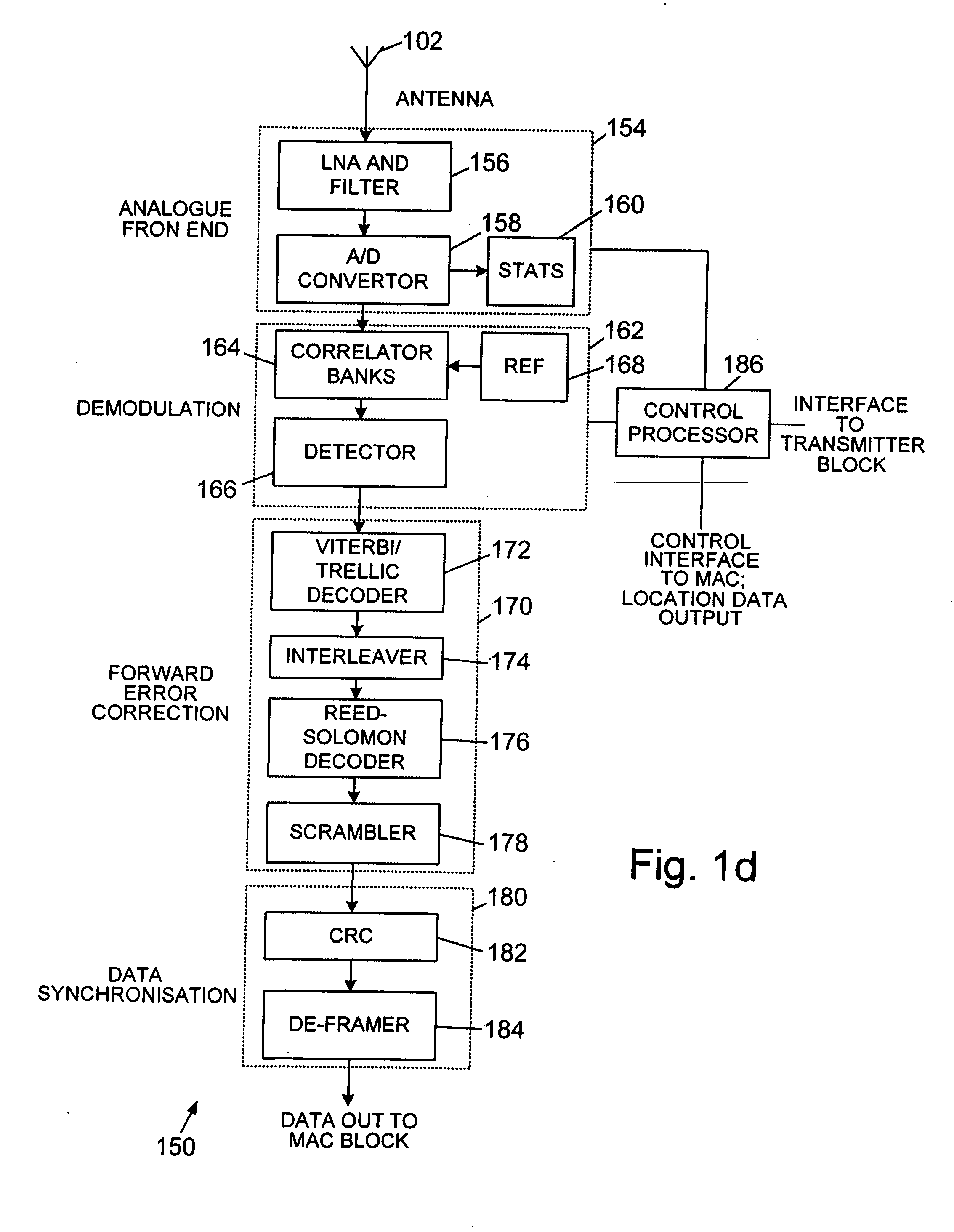
[0023]FIG. 1a shows an example of a UWB transceiver 100 comprising a transmit / receive antenna 102 coupled, via a transmit / receive switch 104, to a UWB receiver 106 and UWB transmitter 108. In alternative arrangements, separate transmit and receive antennas may be provided.

[0024] The UWB transmitter 108 may comprise an impulse generator modulated by a base band transmit data input and, optionally, an antenna driver (depending upon the desired output power). One of a number of modulation techniques may be employed, for example on-off...


PUM


Abstract

A system and method uses near-field or inductively coupled UWB (Ultra Wide Band) systems to implement high speed electrical data connectors without the need for a direct electrical connection. A data connector system has a first connector portion and a second connector portion. The first connector portion comprises a UWB transmitter with a data input and a first UWB coupling element driven by the UWB transmitter. The second connector portion comprises a second UWB coupling element and a UWB receiver with a data output. The UWB receiver has an input from the second UWB coupling element. The data connector system has a connected configuration in which the first and second UWB coupling elements are within an operative range of one another, such that the coupling elements are inductively coupled to one another to permit data to be transferred from the data input to the data output, and a disconnected configuration in which the first and second connector portions are separated by greater than the operative range.

Description

CROSS REFERENCE TO RELATED APPLICATIONS [0001] This application claims priority under 35 U.S.C. 119(e) to U.S. Provisional Patent Application No. 60 / 641,430, filed Jan. 6, 2005 and under 35 U.S.C. 119 to GB Application 0428046.7, filed Dec. 22, 2004, which are both incorporated by reference herein in their entireties.BACKGROUND [0002] 1. Field of the Invention [0003] This invention is generally concerned with the use of near-field or inductively coupled UWB (Ultra Wide Band) systems to implement high speed electrical data connectors without the need for a direct electrical connection. [0004] 2. Related Art [0005] Techniques for UWB communication developed from radar and other military applications, and pioneering work was carried out by Dr G. F. Ross, as described in U.S. Pat. No. 3,728,632, which is incorporated by reference herein in its entirety. Ultra-wideband communications systems employ very short pulses of electromagnetic radiation (impulses) with short rise and fall times, ...

Claims


Application Information

Patent Timeline
Patent Type & Authority Applications(United States)
IPC IPC(8): H04B1/69G06F1/16
CPCG06F1/1632H04B1/7163H04B1/71635H04B1/71637H04B5/0031H04B5/02Y02B60/50
Inventor MOORE, MARK JUSTINLANG, JACK ARNOLDELLWOOD, STEPHEN
Owner ARTIMI
Why Eureka
Try Eureka