
Control information transmission method, relay server, and controllable device

Active Publication Date: 2006-07-20
JVC KENWOOD CORP A CORP OF JAPAN
View PDF12 Cites 43 Cited by
  • Summary
  • Abstract
  • Description
  • Claims
  • Application Information

AI Technical Summary

Benefits of technology

[0059] wherein, when control information on cancellation of timer recording of a program, which is one of programs set up in advance by the control operation

Problems solved by technology

However, even if the video signal recorder, for example, a VCR, can be programmed to record a program remotely, the specified program cannot be recorded satisfactorily if the blank area of recording videotape is insufficient or if the requested recording time overlaps with an already-requested recording time.
However, this method involves cumbersome steps for allocating a recording area for recording a program to be recorded.
Therefore, global IP addresses are limited and all apparatuses connected to the Internet cannot have global IP addresses.
Meanwhile, it is difficult for a computer connected to the Internet to connect to a computer connected to a router having the NAT function because of the limitation of the NAT function.
That is, the problem is that a computer connected to the Internet cannot start communication with a computer connected to a router.
This problem is the so-called NAT traversal problem.
However, it is difficult for a terminal connected to the Internet to start connection to a controlled device having a private IP address as described above and, even when a router with an extended NAT function is used, the number of connectable apparatuses is limited in many cases.

Method used


Image

  • Control information transmission method, relay server, and controllable device
  • Control information transmission method, relay server, and controllable device
  • Control information transmission method, relay server, and controllable device

Examples


Embodiment Construction

[0071] An embodiment of a control information transmission method, an intermediary server, and a controlled device according to the present invention will be described below with reference to the drawings using a preferred embodiment of the present invention.

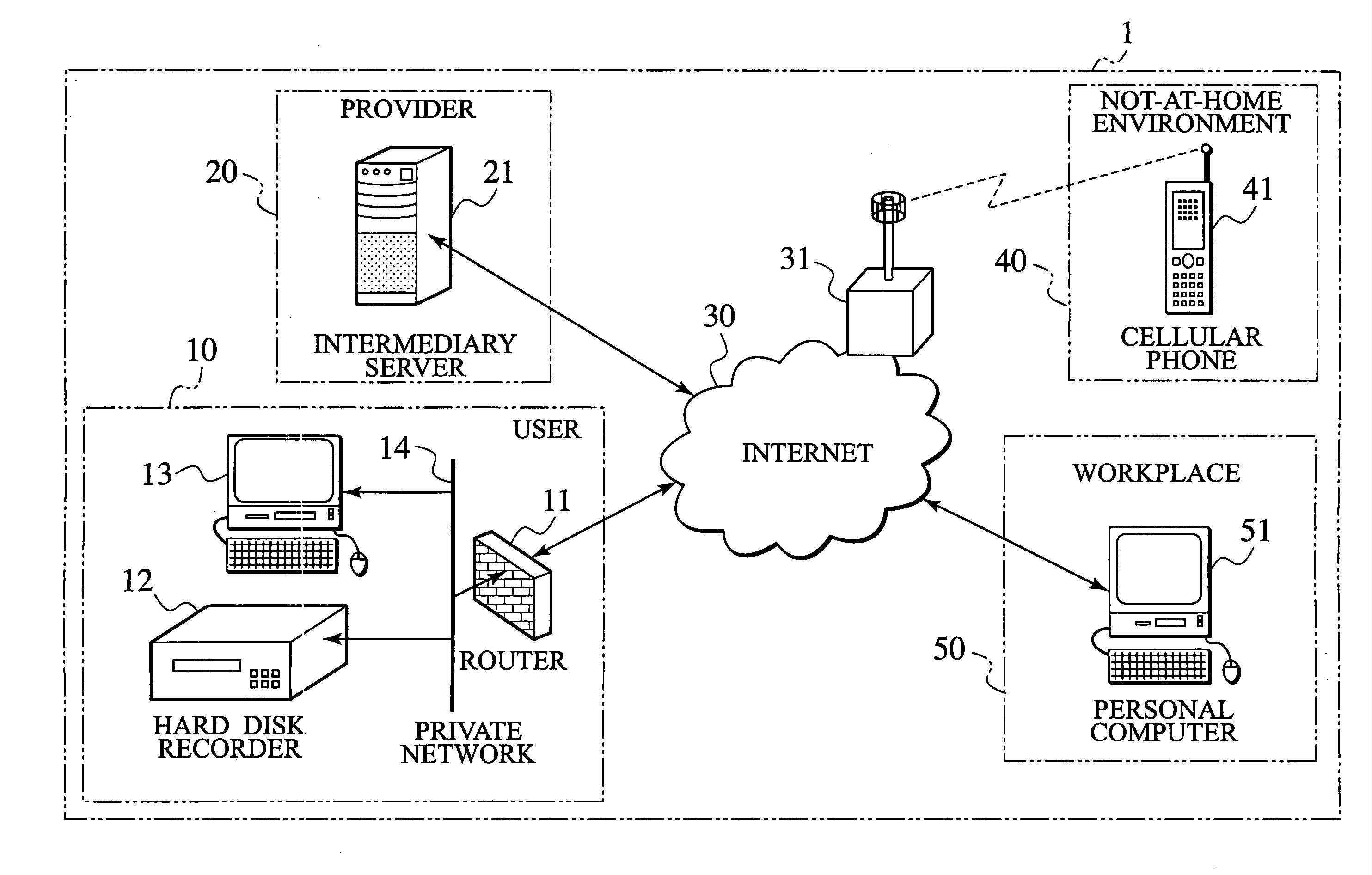
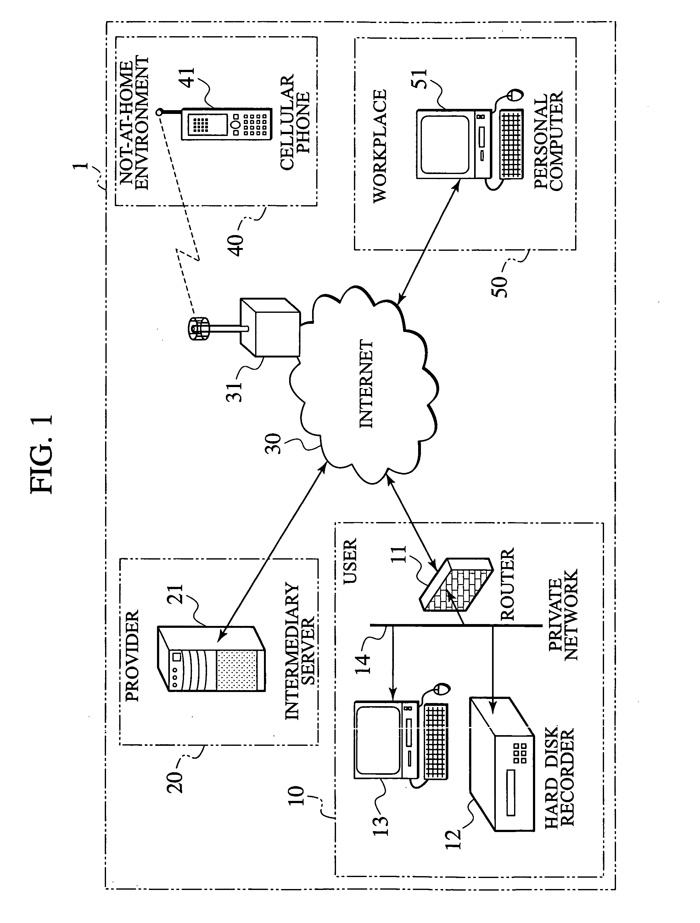
[0072]FIG. 1 shows the general configuration of a timer recording network system in the embodiment.

[0073] A timer recording network system 1 shown in the figure comprises a user environment 10 comprising a router 11, a hard disk recorder 12, a personal computer 13, and a private network 14; a provider 20 where an intermediary server 21 is installed; the Internet 30 where a cellular phone wireless station 31 is installed; a not-at-home environment 40 where a cellular phone 41 is available for use, and a workplace environment 50 where a personal computer 51 is installed.

[0074] Note that the hard disk recorder 12 has a connection terminal for connection to the private network 14 that is configured according to a LAN (Local Area ...


PUM


Abstract

A controlled device (12) sends a signal to a intermediary server (21) at a predetermined time interval, and the intermediary server (21) receives the signal from the controlled device (12) with a private address allocated by a router (11) and changes an operation mode from a passive mode to an active mode. The operation of the controlled device (12) is changed to the passive mode. The intermediary server (21) continuously establishes a communication path with the controlled device (12). The intermediary server (21), which receives control information from a control terminal (41), relays data transmitted via two communication paths, that is, a communication path established with the control terminal (41) and a communication path established with the controlled device (12), to allow the control terminal (41) to control the controlled device (12) operating in the passive mode.

Description

TECHNICAL FIELD [0001] The present invention relates to a control information transmission method executed by an Internet-connected terminal for controlling a controlled device which is connected to a private network connected to the Internet via a router (path selection device) having the NAT (Network Address Translator) function and to which a global IP address is not allocated. The present invention also relates to an intermediary server connected to the Internet for transmitting the control information and to a controlled device controlled by the terminal. BACKGROUND ART [0002] Conventionally, a video signal recorder such as a VCR has been used as a time shift machine that records a broadcast program in advance to allow a viewer to play the recorded program when the view has time to view. A method is also under development for remotely programming a video signal recorder, which is a controlled device, to record a user-requested program, for example, by transmitting an electronic...

Claims


Application Information

Patent Timeline
IPC IPC(8): G06F15/16H04L12/26H04L12/66H04L29/06H04L29/08
CPCH04L29/06H04L67/2819H04L67/125H04L67/28H04L69/329H04L67/564H04L67/56H04L9/40
Inventor KATO, DAISAKU
Owner JVC KENWOOD CORP A CORP OF JAPAN
Learn More