Light rail transport system for bulk materials

a technology for light rail and bulk materials, applied in transportation and packaging, rope railways, ways, etc., can solve the problems of high maintenance cost, high noise of highway trucks, and not very popular with the public, and achieve smooth rotational transition, high wear environment, and prevent leakage

Inactive Publication Date: 2006-07-27
DIBBLE MERTON F
View PDF6 Cites 51 Cited by
  • Summary
  • Abstract
  • Description
  • Claims
  • Application Information

AI Technical Summary

Benefits of technology

[0012] In the present invention there are external or off-track drives that are not physically connected to the moving train limiting the train weight to only the car and load weight reducing the need for costly ballast and sleepers to support the locomotives or drivers required in the conventional railroad comparison. For the purpose of this description light rails are those having a weight of 60 pounds or less per yard of length.
[0042] With the outside loop completed and the cars emptied, it is necessary to rotate the train back to the normal upright position or 180°. The rate of twist is dependent on selected car lengths, and distance available. The longer the distance the smoother the rotational transition with the non-flexible cars. During the twist phase four rails are still required until the car is in its normal operational position. For ease of installation, round steel stock can be substituted for the rail during this application. There is a period of time near the 90° stage of the twist phase that all of the car weight is hanging on the wheel flanges. This is a high wear environment. To compensate for this, a series of rollers are installed that physically contact the side plates and take the weight of the car rather than have the flanges in mechanical contact with the rails. Once the train is inverted after dumping the flexible flaps will again lay flat against the trough of the leading car.

Problems solved by technology

Highway trucks are loud, dangerous, require high maintenance, and are not very popular with the public because of environmentally harmful emissions.
These vehicles, however, are limited to site specific applications and are high capital cost items.
Major off road trucks have evolved that require very wide roadways for passing each other, are not energy efficient per ton-mile of material transported, have limited hill climbing ability, and are dangerous because of potential of operator error as well as being environmentally unpleasant neighbors.
Because of low friction, the use of free rolling iron or steel wheels on steel tracks they are very efficient users of energy but are limited in capacity relative to the drivers or locomotives required.
The inclination capable of conventional railroad systems is limited to the friction between the weighted drive wheels and track.
Spotting cars for both loading and unloading is time consuming and labor intensive.
Although moving from point A to point B by railroad is cost effective the added cost of batch loading and unloading stages in shorter distance transports reduces the rail transport cost effectiveness.
Very long distance single belt runs are very capital cost intensive and are subject to catastrophic failure when the belt tears or rips, shutting down the whole system and dumping the carried load, requiring cleanup.
Conveyor belts are relatively energy efficient but can be high maintenance items because of the inherent problem of multiple idler bearings requiring constant checking and replacement.
Because conveyor belts are very flexible and normally operated fairly flat they are not efficient at transporting moderately high solids slurry that water and fines can accumulate in low spots and spill over the side creating wet spilled slurry handling problems.
It has become apparent however, that increases in labor, energy and material costs plus environmental concerns that alternate transport methods need to be applied that are energy and labor efficient, quiet, non-polluting, and esthetically unobtrusive.

Method used


Image

  • Light rail transport system for bulk materials
  • Light rail transport system for bulk materials
  • Light rail transport system for bulk materials

Examples


Embodiment Construction

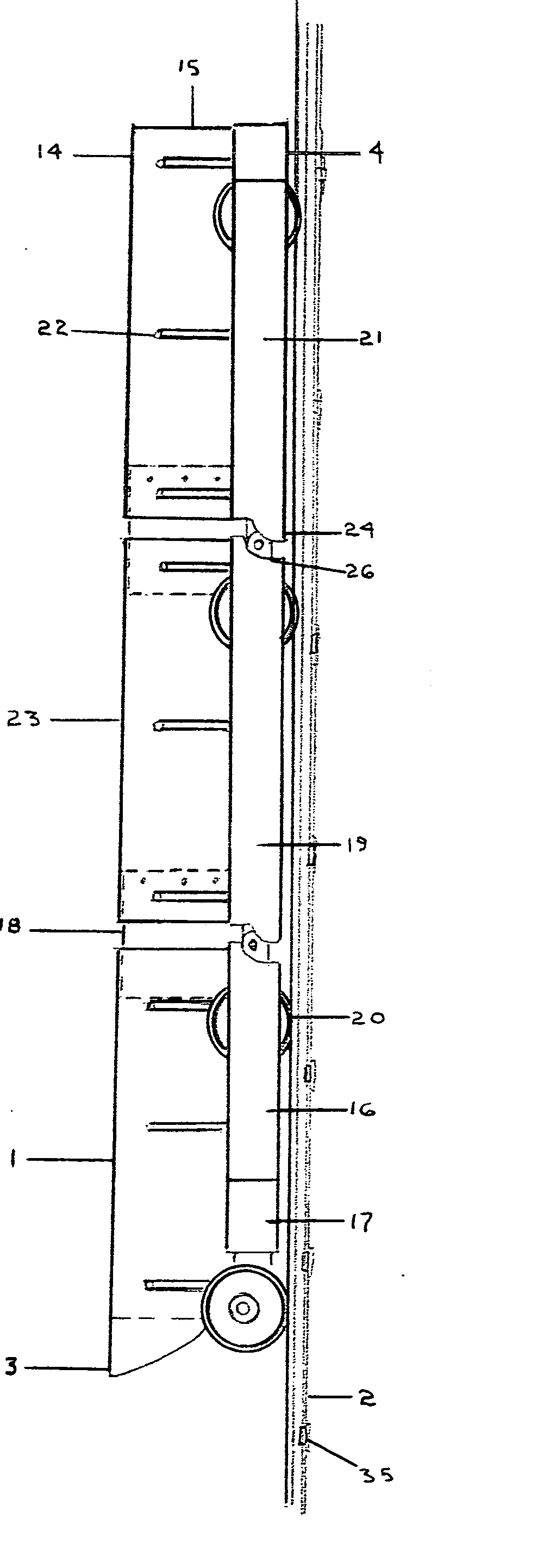
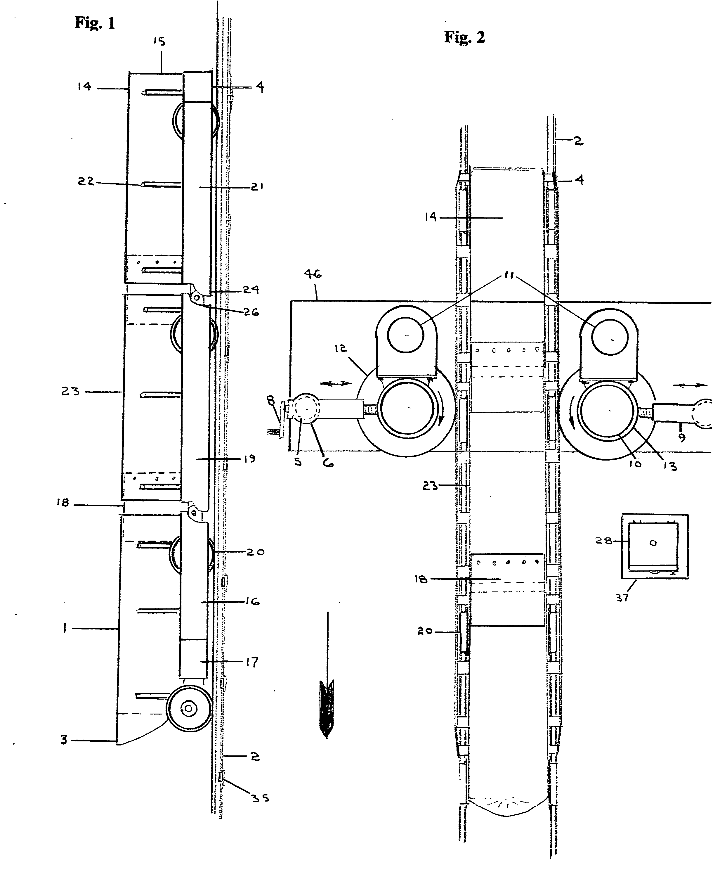
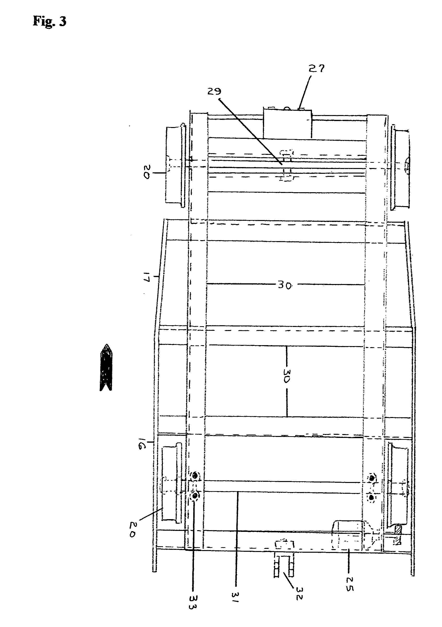
[0055]FIGS. 1-10 illustrate the invention but with regard to the reverence numerals used therein, the following index is presented to facilitate a better understanding of the numbering system used throughout all the figures.

1lead car trough2light rail track3front car discharge chute4rear car drive plate taper5support post for screw-jack6rotational cap for screw-jack7vertical post support brackets8screw-jack mechanicalcontrol handle9screw-jack housing10drive electric motor11pivot post for drive unit12drive tire13drive gear reducer14trough rear car15end plate rear car16front car main drive plate17front car drive plate taper18flexible sealing flap19intermediate cars drive plates20flanged wheel21rear car drive plate22car troughs support saddles23intermediate car trough24drive plate for rotation front25front car system generator26drive plate for rotation rear27safety system alarm pack28control box for A / C inverterfront car29front axle lead car pivot30car frame angle iron supportpin-twi...


PUM


Abstract

A non-powered, light rail unit train (referred to as Rail-Veyor by the inventor) combination for the transport of bulk materials consisting of a plurality of connected cars open at each end except for the first and last cars, which have end plates. The train forms a long open semi-circular trough and has a flexible flap attached near the front of each car, overlapping the gap between car in front to prevent spillage during operation while allowing articulated movement of the train during transport. The lead car has four flanged wheels and tapered side drive plates at the front of the car for smooth entry into the systems stationary drive stations. The cars that follow each have parallel drive plates on either side of the car that are outside the two flanged wheels that are approximately the same width as the flexible drive tire. Each car has a clevis type hitch at the front and rear with the front clevis hitch connecting to the rear clevis hitch of the car immediately forward. Forward motion is provided by a series of appropriately placed fixed drive stations consisting of drive motors, gear reducers and horizontal flexible drive tires located on either side of the track which can be adjusted to provide sufficient friction on the aforementioned drive plates to transform rotational tire motion to horizontal thrust of the entire train. The motors at each drive station are controlled by use of an A / C inverter and controller whereby said motors are synchronized and both the voltage and frequency can be modified as needed to provide and adjust system operating needs. The flanged wheels are symmetrical to the side drive plates allowing operation in an inverted position which, when four rails are used to encapsulate the wheel outside loop discharge of the bulk material is possible. By using elevated rails, the train can operate in the inverted position as easily as in the convention manner.

Description

BACKGROUND OF THE INVENTION [0001] This invention relates to a method and apparatus for moving bulk materials that can be moved in conventional trains, trucks, conveyor belts, aerial tramways or as a slurry in a pipeline. All of the above methods are commonly used in various industries because of site-specific needs or experience. In the minerals and aggregate industries, for example, bulk materials are moved from mining or extraction sites to a process facility for upgrading or sizing. [0002] Trucks had been the system of choice for many years for moving bulk materials. Highway trucks are loud, dangerous, require high maintenance, and are not very popular with the public because of environmentally harmful emissions. Trucks were enlarged to off road vehicles, which are a more efficient transport of bulk materials because of increased capacity. These vehicles, however, are limited to site specific applications and are high capital cost items. Major off road trucks have evolved that r...

Claims


Application Information

Patent Timeline
Patent Type & Authority Applications(United States)
IPC IPC(8): B61J1/06
CPCB61B13/127B65G35/00B65G35/06
Inventor DIBBLE, MERTON F.
Owner DIBBLE MERTON F
Why Eureka
Try Eureka