Device for measuring the electrical activity of biological elements and its applications

a technology of electrical activity and biological elements, applied in the field of electrical activity measurement devices of biological elements and their applications, can solve the problems of insufficient technology, cumbersome implementation, and entirely manual methods, and achieve the effects of reducing manufacturing costs, enhancing flexibility, and improving efficiency

Inactive Publication Date: 2006-07-27
COMMISSARIAT A LENERGIE ATOMIQUE ET AUX ENERGIES ALTERNATIVES
View PDF9 Cites 32 Cited by
  • Summary
  • Abstract
  • Description
  • Claims
  • Application Information

AI Technical Summary

Benefits of technology

[0092] This operating flexibility is further enhanced when the device according to the invention is a modular system, since, in this case, the various modules may be replaced, or on the contrary reused, from one measurement to another or from one series of measurements to another.
[0093] Finally, it can be manufactured very inexpensively, especially when it is in the form of a modular system since...

Problems solved by technology

Although there is no question that the patch-clamp technique, because of its sensitivity, has allowed research to make considerable progress in the understanding of ion channels and has given the pharmaceutical industry a tool for screening molecules that can act on ion channels, it turns out that this technique is not completely satisfactory.
This is because, in the first place, it has the drawback of being very sensitive to the electrical noise and vibrations coming from the surrounding medium and, consequently, of requiring a relatively substantial infrastructure (anti-vibration tables, Faraday cages, etc.) designed to neutralize the interfering effects of such noise and vibration.
Moreover, it is an entirely manual method, which is quite cumbersome to implement, especially because the glass micropipettes that it uses must be prepared, before each measurement, by the drawing and machining of capillaries, and which requires the pres...

Method used


Image

  • Device for measuring the electrical activity of biological elements and its applications
  • Device for measuring the electrical activity of biological elements and its applications
  • Device for measuring the electrical activity of biological elements and its applications

Examples


Embodiment Construction

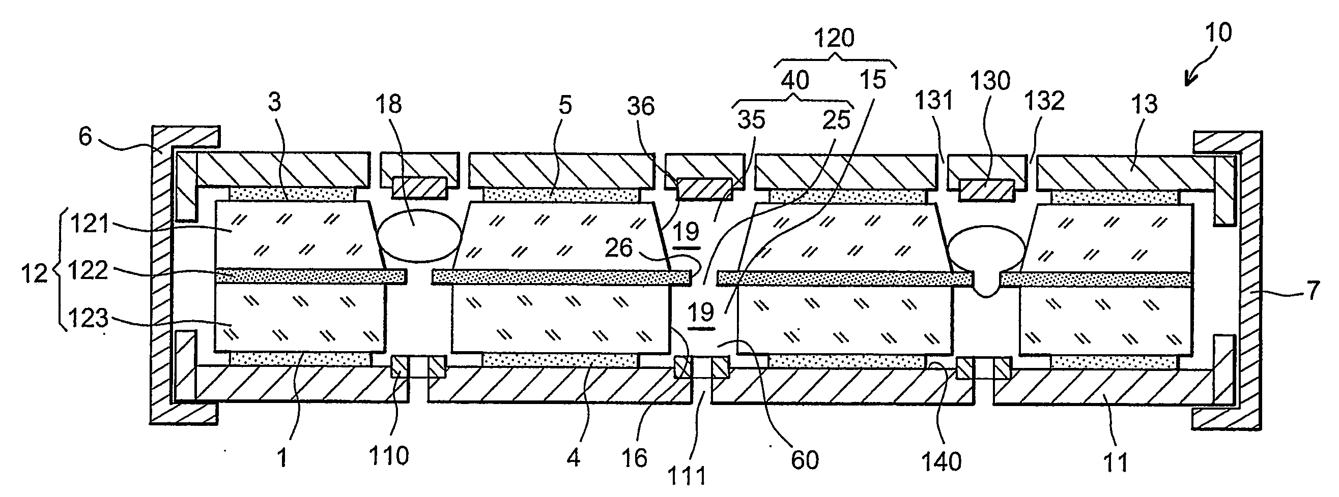
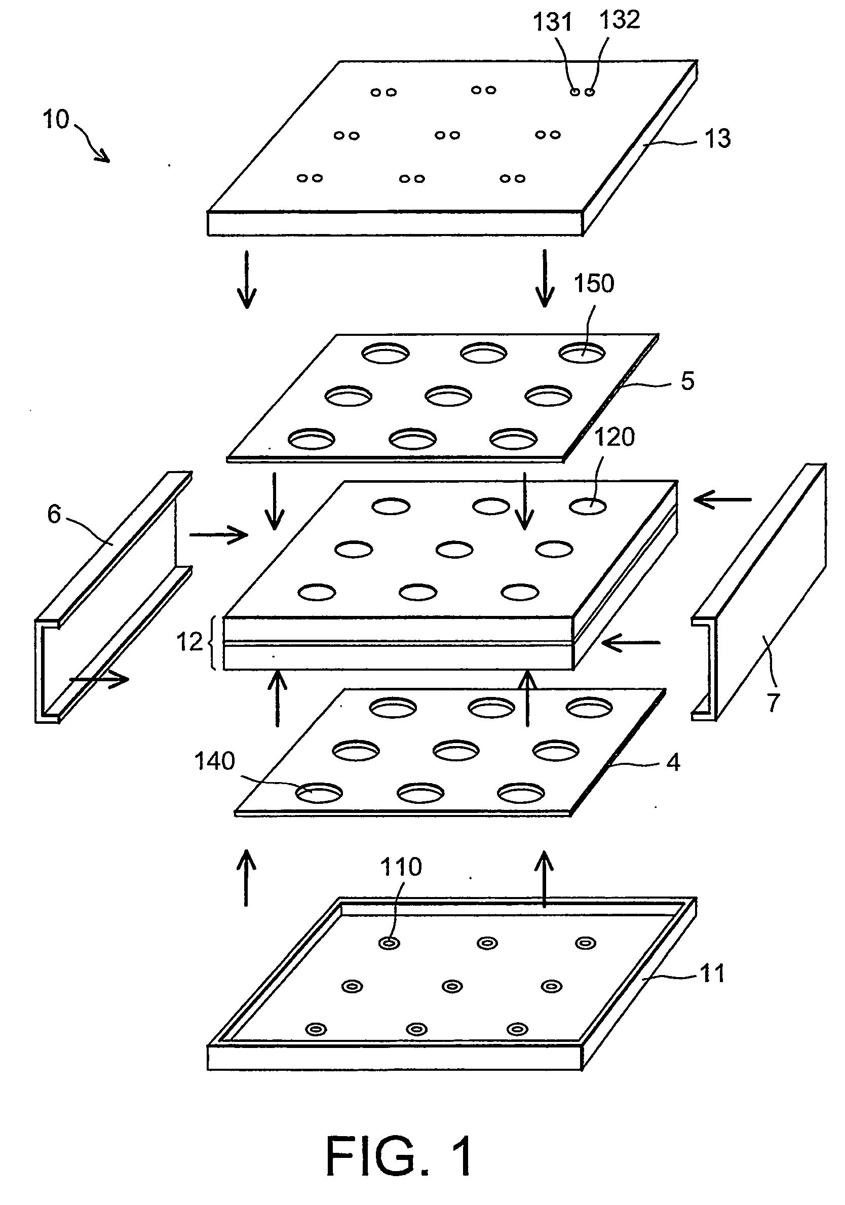
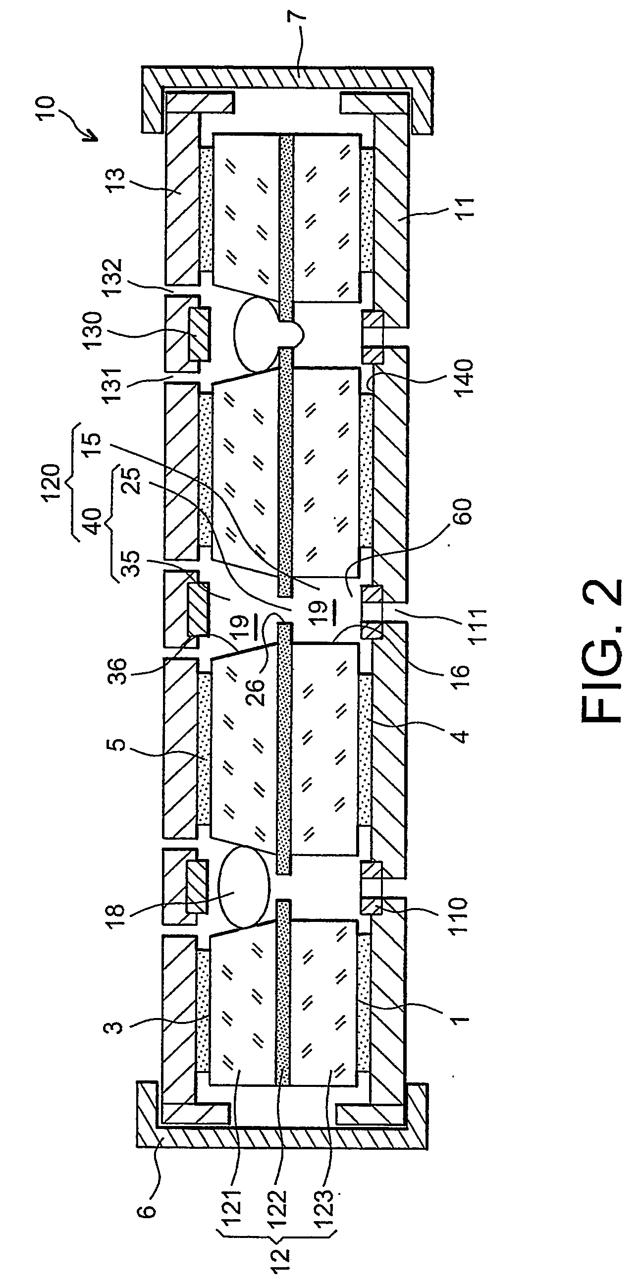
[0111] Referring firstly to FIGS. 1 and 2, these show schematically a device 10 according to the invention in an embodiment designed to allow the electrical activity of nine biological cells to be measured in parallel.

[0112]FIG. 1, which is an exploded perspective view, shows the various components of the device 10 before their assembly, while FIG. 2, which corresponds to a section in the plane P of FIG. 1, shows these same components once they have been assembled.

[0113] As may be seen in FIGS. 1 and 2, the device 10, which is of square general shape, is composed of seven components that can be assembled in a removable manner, namely:

[0114] a first printed circuit 11, which forms the base of this device;

[0115] an approximately plane substrate 12 that is placed on top of the printed circuit 11 and has the function of confining the cells 18 by means of through openings 120 in the substrate;

[0116] a second printed circuit 13, which is itself placed on top of the substrate 12 and f...


PUM

PropertyMeasurementUnit
Diameteraaaaaaaaaa
Diameteraaaaaaaaaa
Diameteraaaaaaaaaa

Abstract

A device for measuring electrical activity of biological elements, including a substrate that has lower and upper faces and at least one through opening, the opening being delimited by a set of walls. Two plates are placed on either side of the lower and upper faces of the substrate and delimit, with the set of walls, a chamber. Each of the plates is provided, on its face lying opposite the substrate, with at least one electrode facing the opening in the substrate. Each of the plates further has at least one channel that starts inside the chamber and connects the chamber to the outside of the device, and the chamber communicates with the outside of the device only through the channels.

Description

FIELD OF THE INVENTION [0001] The present invention relates to a device for measuring the electrical activity of one or more biological elements, and more especially to a device that makes it possible to measure the electrical activity of a plurality of biological elements in parallel. [0002] It also relates to the applications of this device. [0003] In the above and in what follows, the term “biological element” is understood to mean any natural or artificial element at least part of which is formed from a biological membrane or reproduces the structural and / or functional characteristics of a biological membrane. [0004] Thus, it may be a whole biological cell or a biological cell organelle of the type comprising a vacuole, Golgi apparatus, mitochondria, endoplasmic reticulum, lysosome, etc., a biological membrane fragment, possibly furnished with cytosolic components, an artificial lipid bilayer, such as a phosphatidyl choline or phosphatidyl glycerol film, said bilayer being provi...

Claims


Application Information

Patent Timeline
IPC IPC(8): G01N33/487C12Q1/00G01N27/30B01L3/00C12M1/00G01N27/22G01N27/416G01N37/00
CPCB01L3/5085G01N33/48728
Inventor PICOLLET-DAHAN, NATHALIECAILLAT, PATRICEREVOL-CAVALIER, FREDERICCHATELAIN, FRANCOISSAUTER, FABIEN
Owner COMMISSARIAT A LENERGIE ATOMIQUE ET AUX ENERGIES ALTERNATIVES
Why Eureka
Try Eureka