Method for soil remediation and engineering

a soil remediation and engineering technology, applied in the direction of liquid/fluent solid measurement, fluid pressure measurement, peptide, etc., can solve the problems of contaminated soils and groundwater at industrial, waste disposal and spill sites, serious environmental problems, and migration of colloidal fractions, so as to improve the engineering properties, reduce the energy requirement, and reduce the effect of contaminated soils

Inactive Publication Date: 2006-07-27
UNIVERSITY OF BRIGHTON +1
View PDF5 Cites 15 Cited by
  • Summary
  • Abstract
  • Description
  • Claims
  • Application Information

AI Technical Summary

Benefits of technology

[0018] The method of the present invention thus emulates these natural iron′″ mineralisation processes, but over experimental rather than geological time scales, by applying a direct electric potential to electrodes to grow bands of iron′″ mineral phases in sediment and soil columns, and to harness their adsorptive properties, to trap or break down contaminants from the aqueous phase, or extracted from soil particles, during their migration in the applied electrokinetic field. Freshly precipitated amorphous or poorly crystalline Fe-rich solids, of the type generated by this method, are extremely effective scavengers of a range of heavy metals, radionuclides and organic polluants in a variety of environments (Bendell-Young and Harvey 1992, Cundy and Croudace 1995). Zero valent iron is itself an important catalyst for the dechlorination of toxic chlorinated aliphatic compounds (Haran et al., 1996). Moreover, because this method generates strongly acidic conditions at the anode and strongly alkaline conditions at the cathode, contaminants attached to soil or sediment particles (such as radio nuclides and heavy metals), which are soluble under either acidic or basic conditions are solubilised and forced to migrate towards the appropriate electrode, whence they precipitate or are co-precipitated with the iron-band. In essence, the present invention provides the opportunity to “flush” contaminants from parcels of contaminated sediments, and then retrap and concentrate them in, or adjacent to, the iron-band. This offers the potential of in situ clean-up of contaminated soils, sediments and sludges. Clean-up of the whole soil volume between the electrodes can be achieved, and plating of contaminants onto the cathode avoided, by simply reversing the polarity of the electrodes at regular intervals.
[0019] The approach embodied in the method of this invention is distinct from existing in situ remediation technologies, such as permeable reactive barriers, in that rather than merely sequestering contaminants from solution, the system actually mobilises contaminants into solution prior to their subsequent trapping by the reactive band / imposed Eh / pH gradient, thus cleaning contaminated soils as well as ground waters. It differs from existing electrokinetic techniques in its use of low-cost electrodes (for example, electrodes made of cast iron, scrap iron, stainless steel or other iron-rich material), its low energy requirements and most significantly in its deliberate generation of a sorptive iron-band in the material being treated. Hence, the electrokinetic technique described here is innovative and clearly distinguished from other electrokinetic treatment systems. The precipitated iron band, however, represents much more than merely a chemical sink for toxic contaminants liberated from the sediment column via oxidation-reduction and pH reactions. The electrokinetic process that triggers iron band formation may also be used to improve the engineering properties, and massively reduce the permeability, of soils and sediments through differential dewatering of clays, and iron-band generation. Hence, electrokinetic ferric iron precipitation represents a means of physically confining waste spills, providing a reactive barrier to liquid waste spillages that can be re-sealed and strengthened by periodic applications of electrical current (for instance in physically trapping and sorbing leachate that has percolated through the base liner of a landfill). In addition, the method offers the potential, through strategic dewatering or rewatering of soils and sediments and iron-band generation, to rewater and stabilise soils for civil engineering applications (e. g. in building works). Existing dewatering techniques involve complete dewatering of large-volume slurries (e. g. Lamont-Black 2001), whereas the present technique is applied in situ to strategically rewater or dewater, and strengthen or generally improve the engineering properties of, parcels of soil, and so has a range of potential civil engineering applications (such as dealing with subsidence).
[0020] The method of this invention may have direct applicability in relation to the integrity of land fill liners, permeable reactive barrier technologies, and funnel and gate systems, controlled differential subsidence, improving the engineering properties of soils and sediments, remediation of contaminated land (soils and sediments) and clean up of contaminated industrial sludges and slurries. Consequently, it will be of significant interest and potential benefit to a wide range of organisations, for example environment agencies, water companies, land fill operators, civil engineering and environmental consultants and nuclear fuel companies.
[0021] The method of the present invention therefore has a number of surprising and significant benefits compared to other commercial techniques. In comparison with permeable reactive barrier technologies, it provides a resealable iron-rich barrier, which can be remotely placed (without engineering) at working sites and sites with infrastructure to physically and chemically inhibit subsurface pollutant migration, and can redirect subsurface pollutant flow. In comparison with commercial electrokinetic remediation techniques it has an order of magnitude lower energy requirements and electrode cost, does not involve the use of potentially toxic conditioning solutions, can remobilise contaminants from the solid phase and simultaneously trap and contain contaminants in the liquid phase, and can be applied on working sites, or sites containing infrastructure.
[0022] The low voltage used, coupled with the flexibility provided by the use of multiple, low cost electrodes, means that contaminated land can be sequentially treated with a series of electrode arrays, whereby the distance between individual electrodes does not exceed a few metres. In addition, the current is sufficiently low to avoid soil heating and large-scale gas generation at the electrodes. Adjustable electrode geometry means that the technique can be adapted to suit site-specific conditions, and large areas of land can be sequentially treated. It will be appreciated that the iron may be precipitated to form an impermeable coherent band, or a coating which cements soil / sediment particles, or a dispersed coating on mineral grains, between two or more electrodes. Following treatment, the iron band can simply be excavated as a coherent mass, or left in situ to provide a long-term inert, and, via reapplication of current, resealable barrier.
[0023] The method of this invention provides an in situ, sustainable, cost-effective electrokinetic technology for groundwater protection and soil remediation, which can be operated in combination with, or as an alternative to, existing land remediation technologies. The technique is applicable to small sites, as well as larger areas of contaminated land, and can be implemented in ground where man-made structures are present, or where there is on-going site activity.

Problems solved by technology

Contaminated soils and groundwater at industrial, waste disposal and spill sites are serious environmental problems.
It also causes electrophoresis, which results in the migration of colloidal fractions.
However, most contaminated sites contain mixtures of wastes rather than single contaminants and which makes remediation more complicated.
At present there is no standardised universal soil / sediment remediation approach.
Many of these technologies are technically complex and energy intensive, and geared toward the removal of 90% or more of specific contaminants, under very specific field or laboratory-based conditions.

Method used


Image

  • Method for soil remediation and engineering
  • Method for soil remediation and engineering
  • Method for soil remediation and engineering

Examples


examples

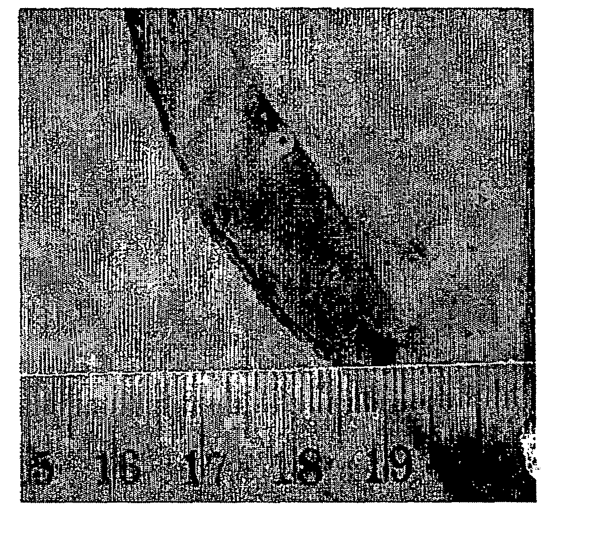
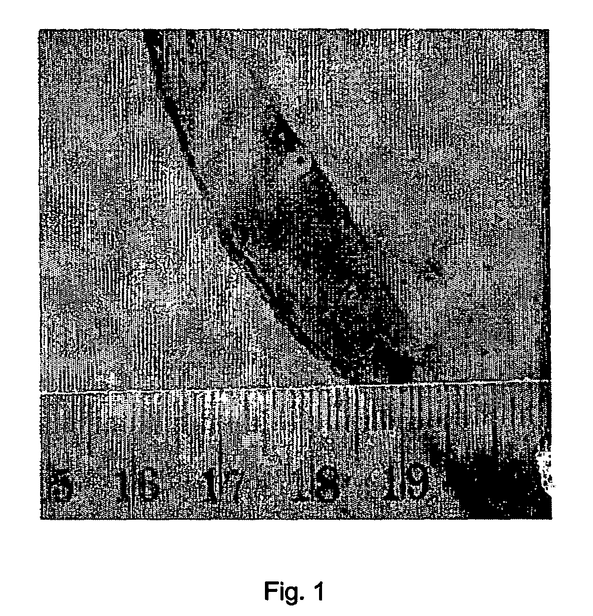
[0030] Pilot studies have been applied at laboratory scales in 25×2×15 cm and 30×50×40 cm open topped perspex cells (i. e. effectively in two dimensional and three dimensional space). All experiments have been run at <5 volts, using sacrificial cast iron electrodes. Electrodes were fabricated from 25 mm diameter cast iron rods (Grade 250), composition: C 3.48%, Si 2.87%, Mn 0.812%, S 0.099%, P 0.364%, Fe REM. Experiments have been run on a variety of contaminated muds, with groundwater and seawater interstitial pore waters, under unsaturated and saturated conditions. Time scales range from 3 to 400 hours.

[0031] In experiments using sand, the initial permeability of the sands was 0.48×10⁻⁵ m / s, post-treatment permeability (in the iron band) was recorded at 0.19×10⁻⁵ m / s. For the mud experiments, initial permeability was typically ˜0.29×10⁻⁷, whereas treated material permeability (in the iron band) was recorded at 10−9, or less, i.e. practically impervious. In addition, clear dewater...


PUM

PropertyMeasurementUnit
distanceaaaaaaaaaa
thickaaaaaaaaaa
voltageaaaaaaaaaa

Abstract

An electrokinetic method for groundwater protection, soil remediation and engineering which comprises applying an electric field across an area of soil, sediment or slurry so as to generate a pH and Eh gradient and thereby promote the in situ precipitation of a stable iron-rich band. The method may be performed for the purpose of stabilisation and/or strategic dewatering/rewatering of soils, sediment and/or slurries, the improvement of the physical properties of soils and sediments for engineering purposes, the forced and directed migration of contaminated leachates, and/or electro-osmotic purging of non-polar contaminants.

Description

FIELD OF THE INVENTION [0001] This invention relates to an electrokinetic method for groundwater protection, soil remediation and engineering, and, more particularly, to such a method which involves the strategic electrokinetic placing of an iron-rich barrier in soils, sediments and slurries. BACKGROUND [0002] Contaminated soils and groundwater at industrial, waste disposal and spill sites are serious environmental problems. Although clays and silts tend to sequester large quantities of heavy metals, radionuclides, and selected organic polluants (Kovalick 1995), they are relatively resistant to remediation with traditional technologies (e. g. pump and treat, soil washing) because of their low hydraulic conductivities. This has stimulated a considerable amount of research into cost-effective, in situ techniques that can be used to remediate low-permeability, high clay content soils. One emerging technology that has received much attention is electrokinetic remediation. Electrokinetic...

Claims


Application Information

Patent Timeline
Patent Type & Authority Applications(United States)
IPC IPC(8): E04B1/70B09C1/08
CPCB09C1/085
Inventor CUNDY, ANDREW BRIANHOPKINSON, LAURENCE JAMES
Owner UNIVERSITY OF BRIGHTON
Why Eureka
Try Eureka