

Printable electrical conductors
a technology of printed electrical conductors and conductors, which is applied in the direction of dielectric characteristics, conductive pattern formation, inks, etc., can solve the problems of insufficient development of low viscosity compositions and insufficient production of well-defined features with good electrical properties
- Summary
- Abstract
- Description
- Claims
- Application Information
AI Technical Summary
Problems solved by technology
Method used
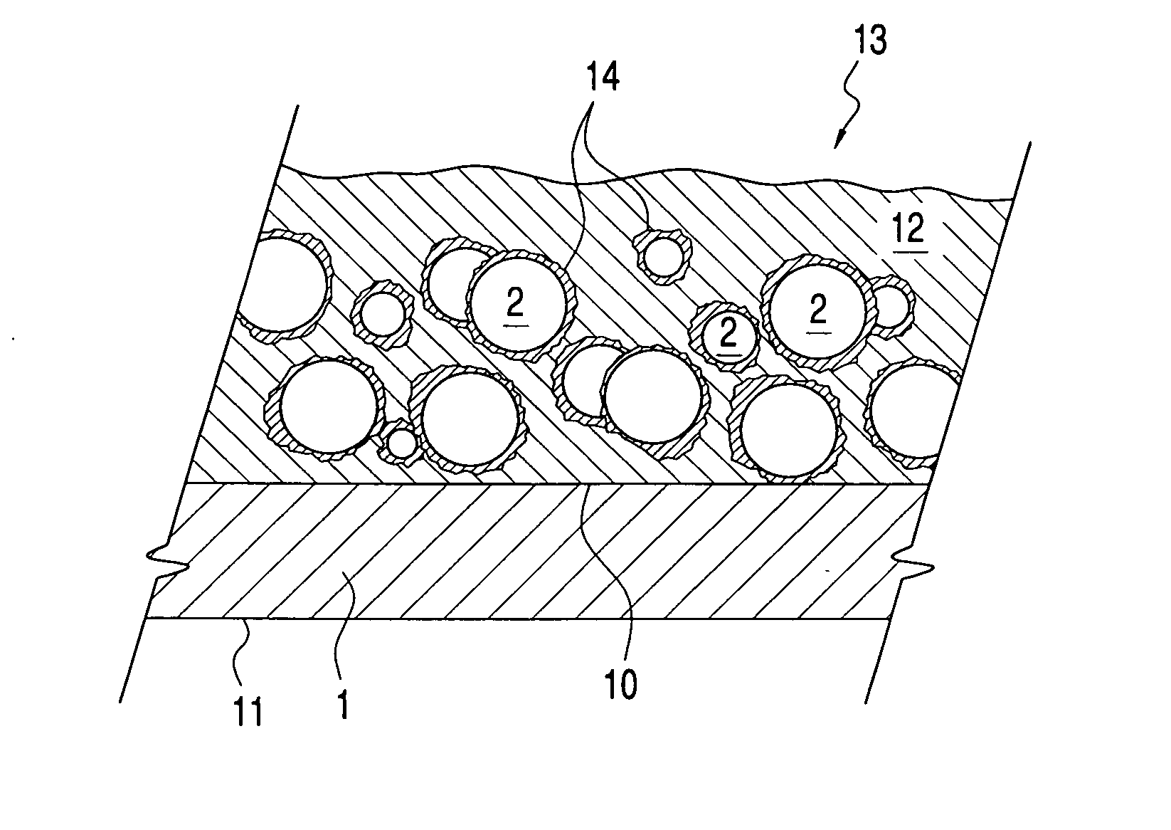
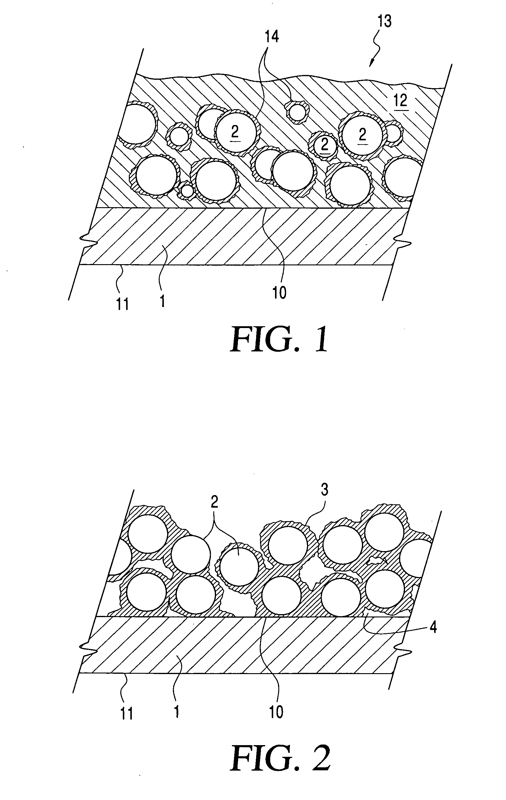
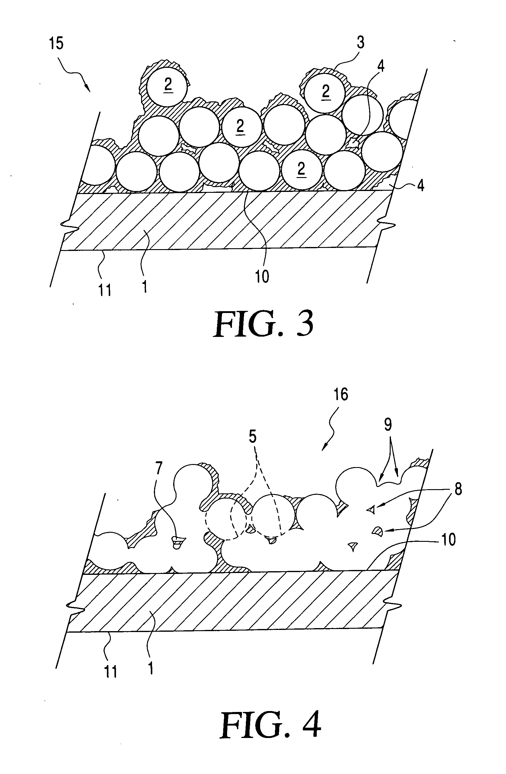
Image

Examples
example 1
A. EXAMPLE 1
Preparation of Silver Nanoparticles Carrying PVP Thereon
[0284] In a mixing tank a solution of 1000 g of PVP (M.W. 10,000, Aldrich) in 2.5 L of ethylene glycol is prepared and heated to 120° C. In a second mixing tank, 125 g of silver nitrate is dissolved in 500 ml of ethylene glycol at 25° C. These two solutions are rapidly combined (within about 5 seconds) in a reactor, in which the combined solutions (immediately after combination at a temperature of about 114° C.) are stirred at 120° C. for about 1 hour. The resultant reaction mixture is allowed to cool to room temperature and about 0.25 L of ethylene glycol is added thereto to replace evaporated ethylene glycol. This mixture is stirred at high speed for about 30 minutes to resuspend any particles that have settled during the reaction. The resultant mixture is transferred to a mixing tank where 12 L of acetone and about 1 L of ethylene glycol are added. The resultant mixture is stirred thoroughly and then transferred...
example 2
B. EXAMPLE 2
Preparation and Testing of Composition for Ink-Jet Printing
[0285] Silver nanoparticles prepared according to the process described in Example 1 (ranging from about 30 nm to about 50 nm in size) are suspended in a solvent mixture composed of, in weight percent based on the total weight of the solvent mixture, 40% of ethylene glycol, 35% of ethanol and 25% of glycerol to produce an ink for ink-jet printing. The concentration of the silver particles in the ink is 20% by weight. The ink is chemically stable for 6 months, some sedimentation occurring after 7 days at room temperature.
[0286] The ink had the following properties:
Viscosity* (22° C.)14.4cPSurface tension** (25° C.)31dynes / cmDensity1.24g / cc
*measured at 100 rpm with a Brookfield DVII+ viscometer (spindle no. 18).
**measured with a KSV Sigma 703 digital tensiometer with a standard Du Nouy ring method.
[0287] 1. Printing and Properties of Printed Features
[0288] A Spectra SE 128 head (a commercial piezo ink-jet he...
example 3
C. EXAMPLE 3
Conductivity Testing of Compositions on Various Paper Substrates
[0305] It was found that the Ag ink composition of Example 2 yields ink-jet printed lines on Epson Gloss IJ ink-jet paper that exhibit an electric resistance after annealing at 100° C. which is comparable to that of the same ink printed on Kapton and annealed at 200° C.
[0306] In one set of tests, the following experiments were carried out:
[0307] An aqueous silver ink was jetted onto glossy IJ photo paper (Canon), producing three groups of 4 lines; 1 set as single pass, 1 set as double pass, and 1 set as triple pass. All three sets were annealed on a hot plate set to 200° C. for 30 minutes. After the annealing, the lines were tested for electrical conductivity; all lines failed to exhibit conductivity.
[0308] The solvent-based Ag ink of Example 2 was printed on EPSON S041286 Gloss photo paper to produce samples for comparison testing with a commercially available Ag ink sample (Nippon Paint) printed on Can...
PUM
| Property | Measurement | Unit |
|---|---|---|
| pore volume | aaaaa | aaaaa |
| pore volume | aaaaa | aaaaa |
| pore volume | aaaaa | aaaaa |
Abstract
Description
Claims
Application Information