Electric motor and apparatus for manufacturing electric motor

a technology of electric motors and motors, which is applied in the manufacture of stator/rotor bodies, magnetic circuits characterised by magnetic materials, and magnetic circuits, etc., can solve the problems of inability to reduce cogging torque, cogging torque, cogging torque, etc., and achieves very efficient reduction of cogging torque, the effect of easy operation and no problems

Active Publication Date: 2006-07-27
FANUC LTD
View PDF11 Cites 21 Cited by
  • Summary
  • Abstract
  • Description
  • Claims
  • Application Information

AI Technical Summary

Benefits of technology

[0050] In the above arrangements, the number of stations is the same as that in the convention case. Thus, it is possible to deal with magnetic anisotropy without increasing the number of stations. Increase in the number of stations makes the entire length of the die set longer, which may make it impossible to carry out punching with a conventional press machine. In these arrangements, however, the number of stations is not increased, and hence, punching can be carried out without problems, very efficiently.
[0051] The present invention can reduce the cogging torque due to magnetic anisotropy of the core plates taking account of teeth of a stator of a motor.

Problems solved by technology

The inventor of this application found that one of the causes of cogging torque is magnetic anisotropy of electromagnetic sheet steel used for forming the rotor and stator.
This magnetic anisotropy of the electromagnetic sheet steel causes cogging torque.
However, what JP 10-66283A intends to remove is variation in rotation caused by torque ripple, which is different from cogging torque.
The inventor of this application found that in addition to the rolling direction, the stator structure can cause cogging torque.
Thus, the inventor of this application found that apart from the rolling direction, the stator structure causes cogging torque, and that if the rolling direction is rotated without taking account of the stator structure, cogging torque cannot be reduced satisfactorily.
Thus, it is difficult to reduce the total cogging torque satisfactorily by the angular displacement of the rolling direction.
Thus, it is difficult to expect reduction of influence of the arrangement of the teeth.

Method used


Image

  • Electric motor and apparatus for manufacturing electric motor
  • Electric motor and apparatus for manufacturing electric motor
  • Electric motor and apparatus for manufacturing electric motor

Examples


Embodiment Construction

[0075] Referring to the drawings, embodiments of the present invention will be described in detail.

[0076]FIG. 11 is a diagram for explaining an example of motor structure. In FIG. 11, a motor comprises a rotor 1 and a stator 2, each having a laminated core structure formed by stacking core plates made of electromagnetic sheet steel.

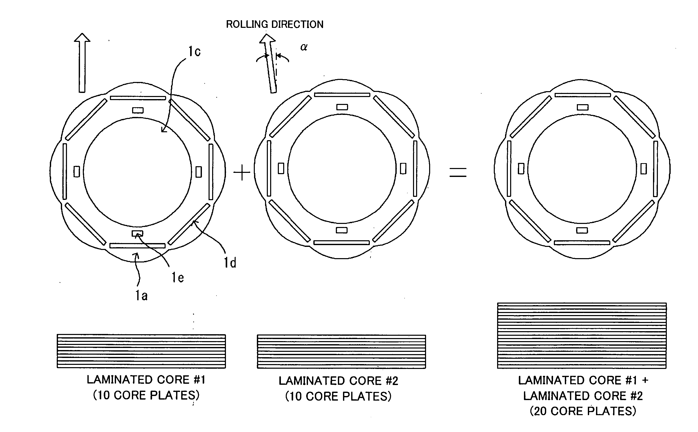
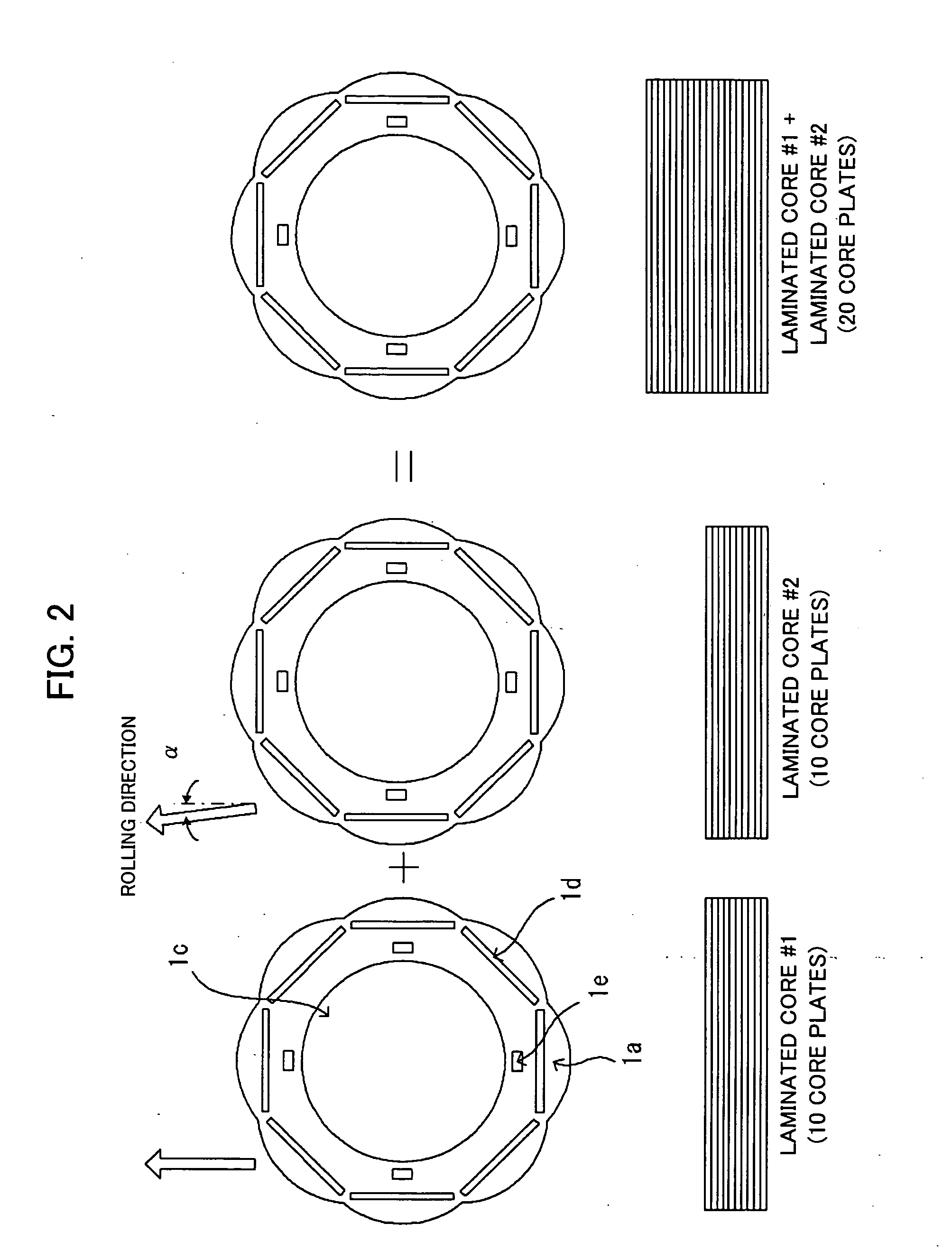
[0077] The rotor 1 is formed by stacking a plurality of rotor cores (core plates) 1a. Each rotor core 1a has an opening in the center for passing a shaft 3, which forms a rotation axis of the motor, through it. Magnet holes 1b, the number of which corresponds to the number of poles of the motor, are arranged equiangularly in the circumferential direction, and permanent magnets are embedded in the magnet holes 1b. The rotor core 1a has also crimps 1e for use in fixing the rotor cores stacked.

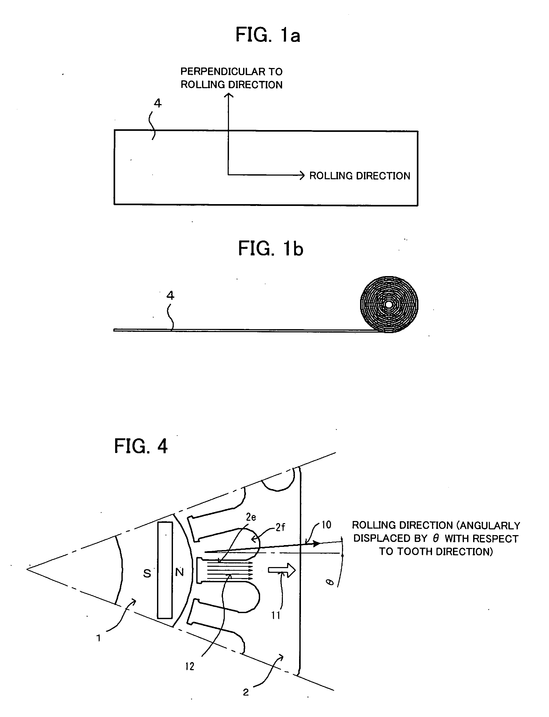
[0078] The stator 2 is formed by stacking a plurality of stator cores (core plates) 2a. Each stator core 2a has an opening in the center for arranging the rotor 1 i...


PUM

PropertyMeasurementUnit
machine angleaaaaaaaaaa
direction angleaaaaaaaaaa

Abstract

A motor capable of reducing cogging torque depending on teeth of a stator, and a motor manufacturing apparatus for manufacturing this motor. The angles of rolling directions of cores stacked are set so that the phase difference between the phases of cogging torques produced on the cores is 180° so that the cogging torques produced on the cores cancel each other to reduce the total cogging torque in the motor. The motor comprises a laminated core formed by stacking a plurality of cores made from a rolled electromagnetic sheet steel. The cores forming the laminated core have rolling directions different from each other by a specified machine angle determined depending on the number of slots and/or the number of poles, where the specified machine angle is an angle which produces a phase difference of 180° between the phases of cogging torques produced due to magnetic anisotropy of the cores and the arrangement of teeth depending on the number of slots and/or poles of the motor.

Description

BACKGROUND OF THE INVENTION [0001] 1. Field of the Invention [0002] The present invention relates to an electric motor and an apparatus for manufacturing an electric motor, and particularly to a technique for reducing cogging torque due to magnetic anisotropy of rolled sheet steel. The present invention is applicable to rotary electrical machines such as motors and generators. [0003] 2. Description of Related Art [0004] In a motor comprising a rotor with magnets embedded and a stator with a coil part formed by winding a wire in slots arranged at regular intervals in the circumferential direction, and driven to rotate by torque produced by the magnets and reluctance torque produced by the coil, cogging torque which makes the rotor pulsate is produced when the rotor rotates. [0005] When the magnetic flux lines produced by the magnets in the rotor form closed magnetic paths passing through teeth of the stator, the sum of electromagnetic attractive forces between the stator and the roto...

Claims


Application Information

Patent Timeline
Patent Type & Authority Applications(United States)
IPC IPC(8): H02K5/24H02K21/12H02K1/00H02K15/14
CPCH02K1/02H02K1/06H02K1/16H02K1/276H02K15/02Y10T29/5317H02K29/03Y10T29/49012Y10T29/49009Y10T29/53143H02K15/03Y10T83/2092
Inventor YAMAMOTO, TOMONAGAMAEDA, TAKUYA
Owner FANUC LTD
Why Eureka
Try Eureka