Optical scanning apparatus, optical writing apparatus, image forming apparatus, and method of driving vibration mirror

a technology of optical writing apparatus and mirror, which is applied in the direction of fluid speed measurement, instruments, optical elements, etc., can solve the problems of significant variation in the accuracy of each of the mirror surfaces, and significant affecting the swing angle of the mirror substra

Inactive Publication Date: 2006-07-27
RICOH KK
View PDF11 Cites 27 Cited by
  • Summary
  • Abstract
  • Description
  • Claims
  • Application Information

AI Technical Summary

Benefits of technology

[0029] A general object of the present invention is to provide an improved and useful optical scanning apparatus, optical writing apparatus, image forming apparatus, and method in which one or more of the above-mentioned problems are eliminated.
[0030] Another and more specific object of the present invention is to provide an optical scanning apparatus using an electrostatically-actuated beam-supported-type vibration mirror, an optical writing apparatus and an image forming apparatus using the optical scanning apparatus that can effectively suppress variation of a swing angle of a vibration mirror caused by, for example, change in environmental temperature, without changing the structure of a vibration mirror and without providing additional means that increase costs, thereby achieving stable optical scanning and stable image formation.
[0031] Still another object of the present invention is to provide a method that reduces variation in the resonance frequency of a vibration mirror and a method that increases the tolerance range for variation in a driving frequency.

Problems solved by technology

In addition, since a polygon mirror uses a plurality of mirror surfaces, there is a problem of variation in accuracy of each of the mirror surfaces.
However, as can be seen from FIG. 14 showing measurement results, the above-mentioned vibration mirror has a problem in that the swing angle (vibration amplitude) of the mirror substrate is significantly varied when environmental temperature is changed.
The problem is caused since the resonance point of a vibrating system of a vibration mirror varies depending on environmental temperature and the variation of the resonance point significantly affects the swing angle of the mirror substrate.
However, it is undesirable in terms of reliability to provide an electric resistive element in a beam that is elastically deformed.
Additionally, when the electric resistive element is provided, the manufacturing process of a vibration mirror is complicated, and additional means are required for controlling a current of the electric resistive element, which are problems in terms of costs.
In order to achieve a higher resolution image and high-speed printing, it is necessary to further increase the moving speed of the mirror, which may present problems in durability of a bearing supporting the mirror, heat generation due to windage loss of the mirror, and noise, for example.
Thus, there is a limit for such conventional optical scanning apparatuses to perform high-speed scanning.
However, the swing angle of the vibration mirror is small, and there is a limit to the size of a reflection surface.
However, when using a plurality of vibration mirrors and scanning in a divided manner as mentioned above, variation in the resonance frequency of each of the vibration mirrors may become a major problem.
This is because when the variation in the resonance frequency is large, it is difficult or impossible to drive the plurality of vibration mirrors with a common driving frequency.
Accordingly, the above-mentioned problem cannot be avoided, and it is necessary to select one of the following options: for example, driving the vibration mirrors with respective driving frequencies corresponding to respective resonance frequencies; selecting and using those vibration mirrors that fall within a predetermined range, and driving the vibration mirrors with the same driving frequency, which is undesirable in terms of process yield; and adding a complicated driving system whereby controlling and driving the vibration mirrors.
However, since the above-mentioned method performs the adjustment in the middle of the manufacturing process, there are problems in that a shift tends to occur if adjustment is not performed in prospect of a difference between the resonance frequencies before and after completion of the vibration mirror, and it is difficult or impossible to correspond to variation in the resonance frequency under an environment subjected to the above items (ii) and / or (iii).
However, there are problems in the above-mentioned method.
In addition, since electricity is continuously conducted to the heater, power consumption also is increased.
Further, since the temperature of the elastic member is controlled by heat generation of the heater, there is a problem in that it is difficult or impossible to correspond to decrease in environmental temperature in a positive manner.
Hence, it is doubtful whether it is possible to design a vibration mirror such that the above-mentioned stress is effectively generated, and whether the stress is effectively generated as designed, when considering errors inevitably introduced during the production of the vibration mirror.
However, the method drives the vibration mirror with an electromagnetic force.
Thus, there is, for example, a limitation that the method is inapplicable to a vibration mirror that uses a driving force other than an electromagnetic force.

Method used


Image

  • Optical scanning apparatus, optical writing apparatus, image forming apparatus, and method of driving vibration mirror
  • Optical scanning apparatus, optical writing apparatus, image forming apparatus, and method of driving vibration mirror
  • Optical scanning apparatus, optical writing apparatus, image forming apparatus, and method of driving vibration mirror

Examples


first embodiment

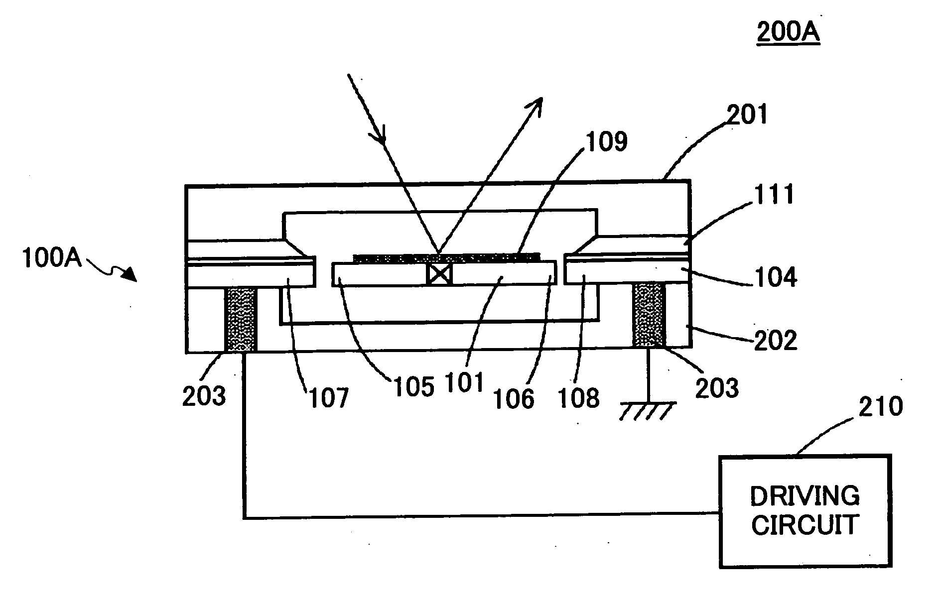
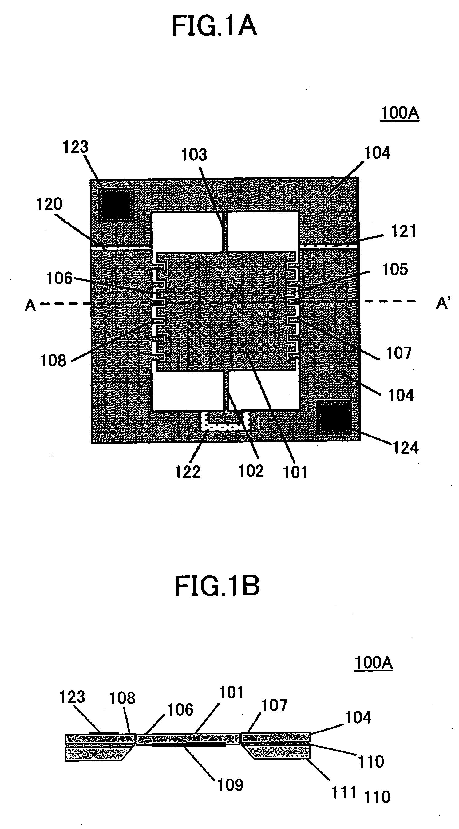
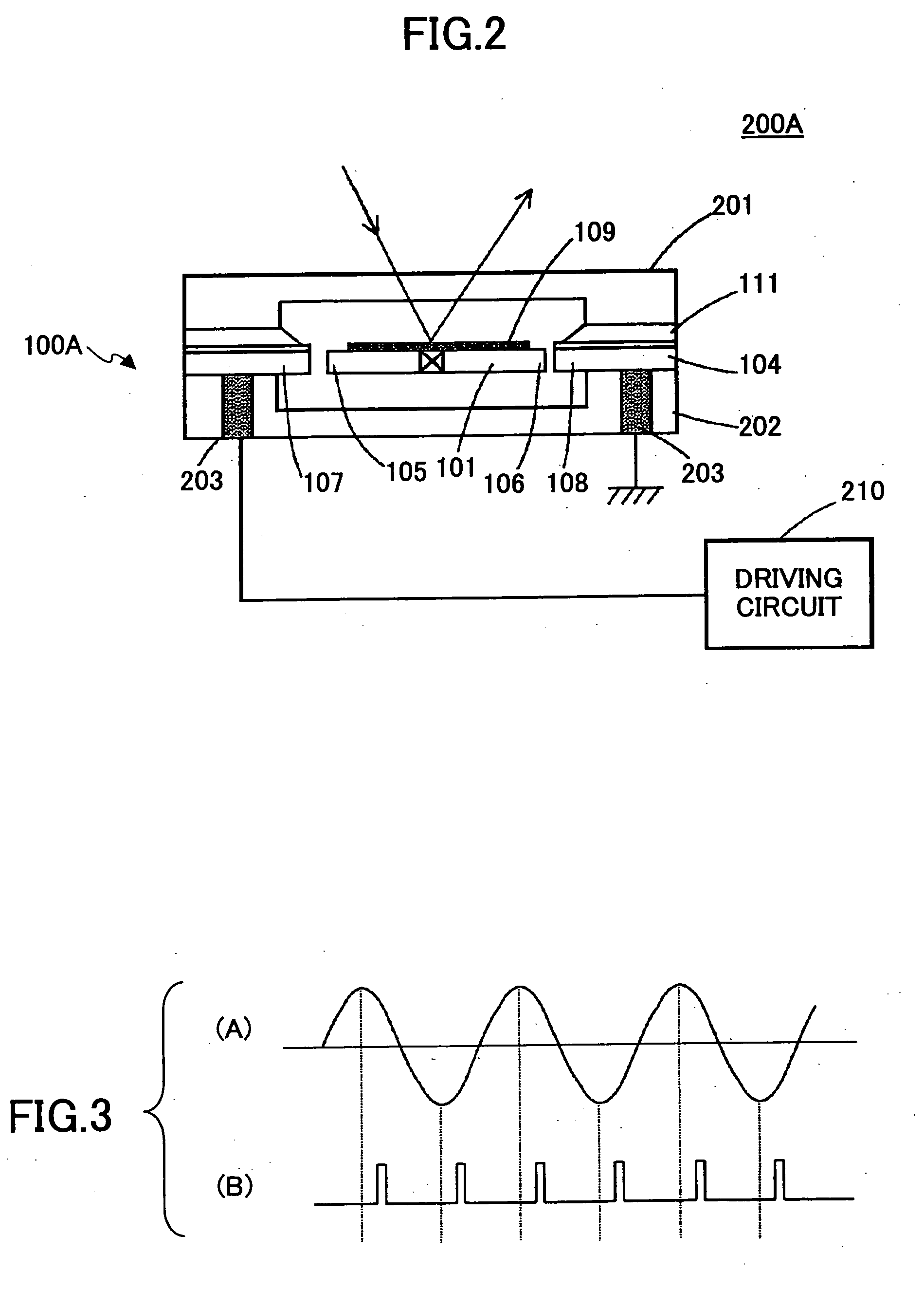
[0218] A description is given below of the first embodiment of the present invention. FIGS. 1A and 1B show the structure of a vibration mirror 100A used in an optical scanning apparatus 200A according to this embodiment. FIG. 2 shows the general structure of the optical scanning apparatus 200A.

[0219]FIG. 1A is a schematic plan view of the vibration mirror 100A seen from the side opposite to a mirror surface of the vibration mirror 100A. FIG. 1B is a schematic cross sectional view of the vibration mirror 100A taken along the line A-A′ in FIG. 1A.

[0220] The vibration mirror 100A shown in FIG. 1A includes a mirror substrate 101, torsion beams 102 and 103, and a frame supporting part 104. The mirror substrate 101 is supported by the frame supporting part 104 via the torsion beams 102 and 103 at the central portions of two opposing ends thereof. The mirror substrate 101 can perform reciprocating vibration while using the torsion beams 102 and 103 as the torsion rotation axes. Comb-like...

second embodiment

[0230] A description is given below of a second embodiment of the present invention. FIGS. 6A, 6B and 6C show the structure of a vibration mirror 100B used in an optical scanning apparatus 200B according to this embodiment. FIG. 7 shows a general structure of the optical scanning apparatus 200B.

[0231]FIG. 6-(A) is a schematic plan view of the vibration mirror 100B seen from the side opposite to the mirror surface 109. FIG. 6-(B) is a schematic cross-sectional view of the vibration mirror 100B taken along the line A-A′ in FIG. 6-(A). FIG. 6-(C) is a schematic plan view of the vibration mirror 100B seen from the mirror surface 109 side.

[0232] In FIG. 6, those parts that are the same as those corresponding parts in FIG. 1 are designated by the same reference numerals. The vibration mirror 100B of the second embodiment structurally differs from the vibration mirror 100A of the first embodiment in that: second comb-like driving electrodes (driving electrodes) 112 and 113, which overlap...

third embodiment

[0241] According to a third embodiment of the present invention, the driving circuit 230 may drive the vibration mirror 100B at a vibration frequency similar to that in the second embodiment by applying the driving pulse as shown in FIG. 10 to each of the electrodes 107, 108, 112 and 113. In FIG. 10, (A) represents the vibration waveform of the mirror substrate 101, (B) represents the waveform of the driving pulse applied to the driving electrodes 107 and 108, (C) represents the waveform of the driving pulse applied to the driving electrode 112, and (D) represents the waveform of the driving pulse applied to the driving electrode 113.

[0242] The driving pulse is applied to the driving electrodes 107 and 108 when the swing angle is equal to or less than θo. When the swing angle exceeds θo, the driving pulse is applied to the driving electrodes 112 and 113. In the third embodiment, however, the driving pulse is applied before and after the extreme value of the vibration waveform. That...


PUM


Abstract

An optical scanning apparatus includes a vibration mirror having a mirror surface that reflects an optical beam. A pair of torsion beams swingably support the mirror. The mirror is vibrated in a sealed space whose pressure is adjusted such that a characteristic of the mirror falls within a predetermined range.

Description

BACKGROUND OF THE INVENTION [0001] 1. Field of the Invention [0002] The present invention generally relates to: micro optical systems applying micro machining techniques; and image forming apparatuses such as digital copying machines and laser printers, and more particularly, to: an optical scanning apparatus using a beam-supported-type vibration mirror driven by an electrostatic force; an optical scanning apparatus that can be applied to, for example, an optical-scanning-type barcode reader and an in-vehicle laser radar; and an image forming apparatus using such an optical scanning apparatus. [0003] 2. Description of the Related Art [0004] The optical scanning apparatus using a beam-supported-type vibration mirror driven by electrostatic force is a promising candidate for an optical writing apparatus of an image forming apparatus such as a digital copying machine and a laser printer, and for an optical reading apparatus such as a barcode reader and a scanner. [0005]“Silicon Torsion...

Claims


Application Information

Patent Timeline
Patent Type & Authority Applications(United States)
IPC IPC(8): G02B26/08B81B7/00
CPCG02B26/0841G02B26/0858G02B26/105
Inventor FUJII, MITSUMIMOCHIZUKI, EIJI
Owner RICOH KK
Why Eureka
Try Eureka