
Coating system

a coating system and coating technology, applied in the direction of coatings, roads, roads, etc., can solve the problems of not working properly, time-consuming and laborious removal of masking materials, and coatings cannot be applied close to no-coat areas

Inactive Publication Date: 2006-08-03
ULTRASONIC SYST GMBH
View PDF8 Cites 20 Cited by
  • Summary
  • Abstract
  • Description
  • Claims
  • Application Information

AI Technical Summary

Benefits of technology

[0020] In one especially preferred embodiment, the system comprises a first coating applicator for coating large areas of the substrate, and a second coating applicator for coating small areas of the substrate. It also comprises a motion and positioning system for both coating applicators and a system controller. In an especially preferred embodiment, this invention utilizes a device to produce very small coating segments in conjunction with the large area coating applicator to eliminate the limitation of currently available selective coating systems that utilize needle in seat dispensing valves.
[0057] This device will typically be attached to an end effector that is part of an X, Y, Z programmable robot that controls the position and speed of the device relative to the substrate, thereby, allowing the user to apply coatings of any desired pattern to the substrate.

Problems solved by technology

If coating is applied to the “no-coat” areas, the circuit board will not function properly due to the presence of the coating.
The application and removal of the masking material is time consuming and labor-intensive.
However, typical large area coating applicators deposit the coating patterns with irregular edges.
The coating cannot be applied close to the no-coat areas with these applicators due to the irregular edge of coating deposition.
These automated systems have been effective in certain circumstances but they do not produce a uniform coating application and have not completely eliminated the requirement for masking.
If these coatings are applied at a greater thickness than is optimal for curing, cracks will form during the drying process, reducing the coating's protective properties.
However, difficulties arise if the same low viscosity coating formulation is used in the dispensing valve.
The dispensing valve produces a bead or line of coating on the substrate and the coating will tend to flow or wet out on the substrate unpredictably with low viscosity coating mixtures.
The use of a low viscosity formulation for the spray applicator and a higher viscosity coating formulation with the dispensing applicator results in a non-uniform coating on the substrate.
Additional limitations of dispensing valves include imprecise flow rate control, difficulty producing short coating lines segments, heavy coating deposition at the start and end of a coating segment and susceptibility to uneven or warped substrate surfaces.
This coupled with the head motion profile tends to produce heavy spots at the start and end of a coating segment and makes is difficult to create a short coating segment.
This effect can somewhat be overcome with programming techniques for the system controller, but this process is tedious and not repeatable.
If the substrate is uneven or slightly warped coating skips may result due to changing distance between the needle and substrate.
Additionally, the needle has a tendency to contact previously applied coating and pull it along with it causing skips and smears.
The needle is also subject to being damaged if it comes into contact with the substrate.
In summary, the limitations of current selective coating systems include: (1) Inability to provide a uniform coating thickness for both large and small areas to be coated.
(3) Manual adjustment of the coating flow rate, which produces inconsistent results, due to subjective process setup.
(4) Difficulty controlling the dispensing process due to unpredictable coating flow-out on the substrate, heavy spots ant the beginning and end of coating segments and susceptibility to irregular substrate surfaces.

Method used


Image

  • Coating system
  • Coating system
  • Coating system

Examples


Embodiment Construction

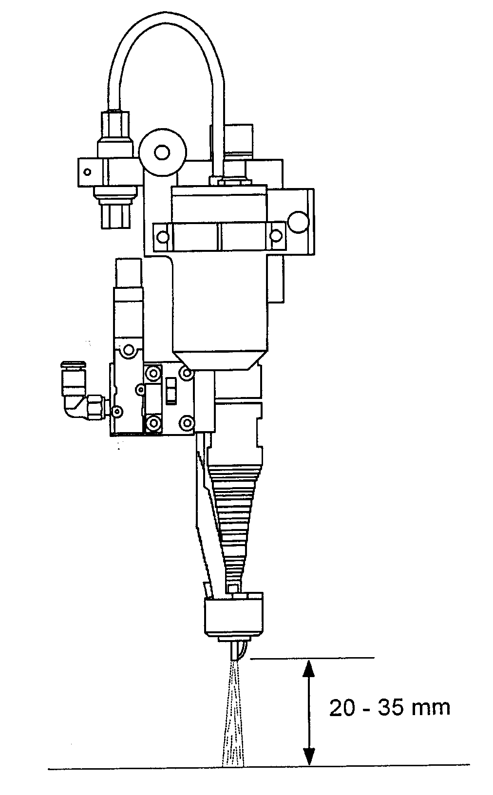
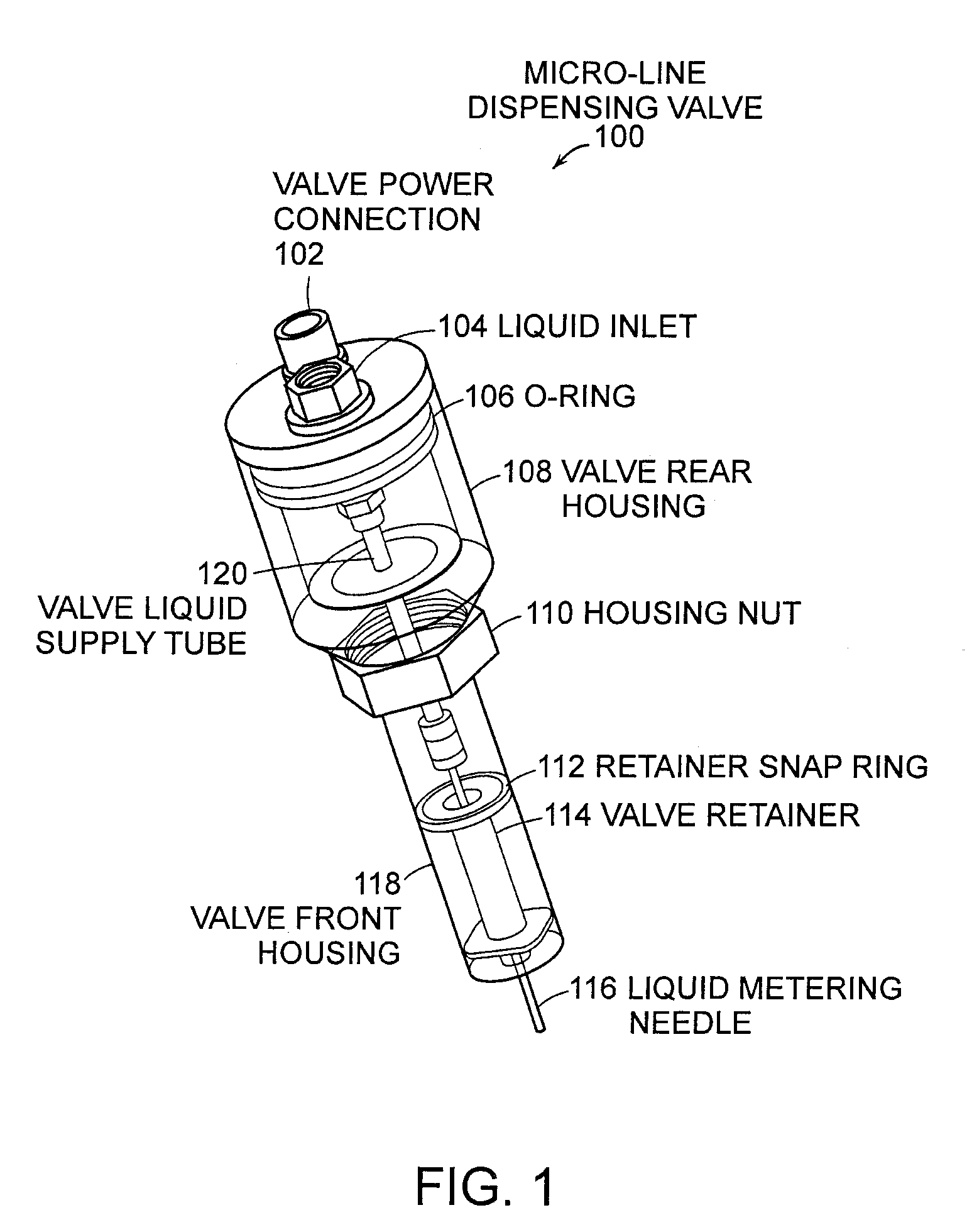
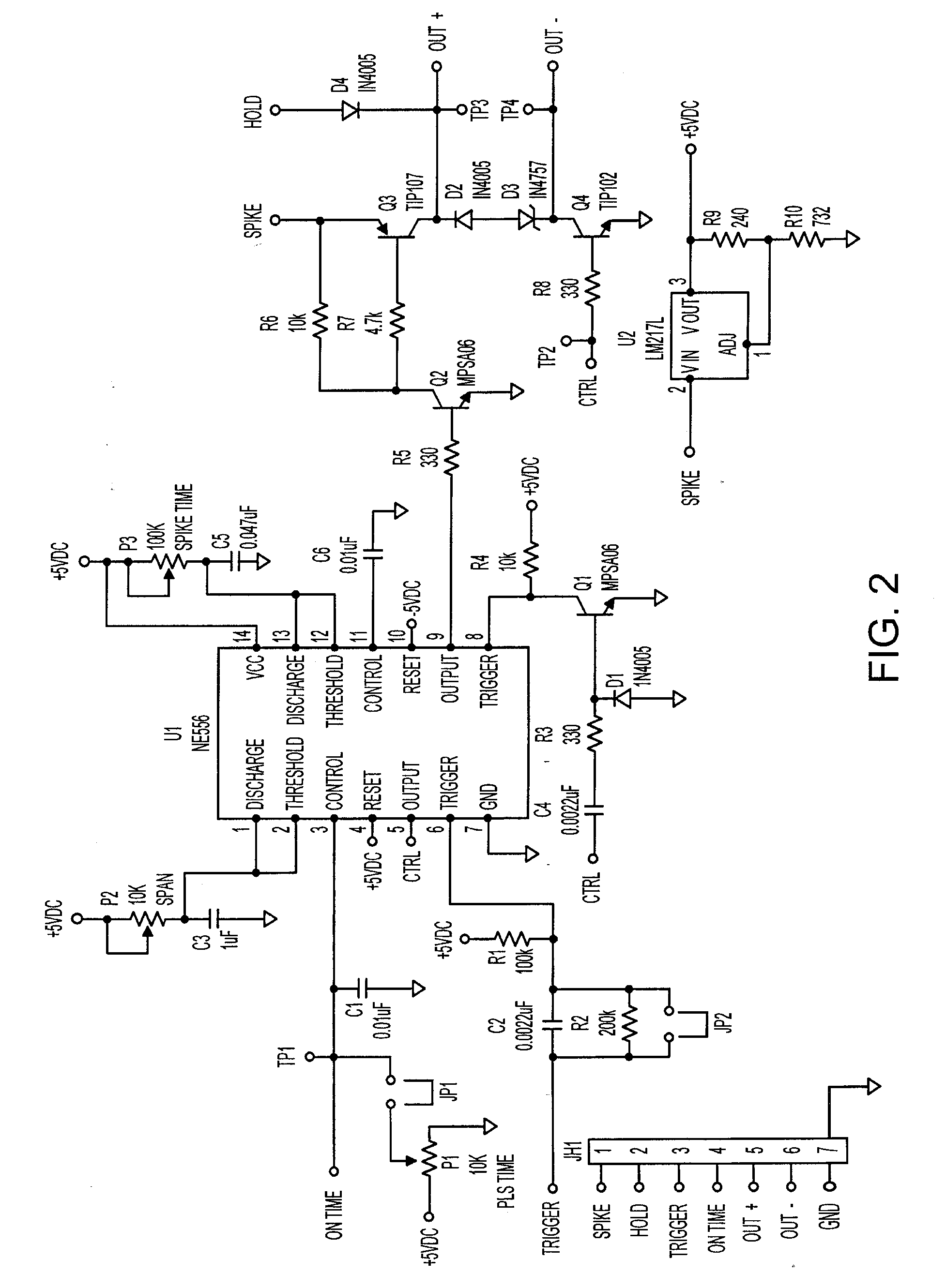
[0072] As depicted in FIGS. 1-4, one embodiment of the present invention comprises a spray coating system for the selective application of coatings to substrates to apply a uniform coating to selected areas of the substrate without the need for masking.

[0073] The preferred embodiment of the system comprises a first coating applicator for coating large areas of the substrate, a second coating applicator for coating small areas of the substrate, a motion and positioning system for both coating applicators and a system controller. The focus of this invention is the integration of a device for producing small coating segments with the other components of the coating system.

[0074] In a preferred embodiment, the first coating applicator—i.e., the applicator for larger areas, is a precision ultrasonic spray head or other large area coating head. The second coating applicator is specifically designed to apply coatings to selected very small areas of a substrate, for example, as small as 1...


PUM


Abstract

Disclosed is a coating system for the selective application of coatings to substrates to apply a uniform coating to selected areas of the substrate without the need for masking. The system comprises a first coating applicator for coating large areas of the substrate, a second coating applicator for coating small areas of the substrate, a motion and positioning system for both coating applicators and a system controller. Also disclosed is an ultrasonic spray coating system comprising an ultrasonic transducer with spray forming head, integrated fluid delivery device with air and liquid supply passage ways, support brackets and an ultrasonic power generator.

Description

CROSS-REFERENCE TO RELATED APPLICATIONS [0001] This application claims priority from copending Provisional Application Serial No. 60 / 643,024, filed 11 Jan. 2005. This application is also a continuation-in-part of application Ser. No. 10 / 927,547, filed 26 Aug. 2004. That application was a continuation-in-part of PCT Application No. PCT / US2004 / 009549 filed 29 Mar. 2004, which designates the United States. The PCT Application claimed priority from commonly owned, copending U.S. Provisional Application Serial No. 60 / 458,487, filed 28 Mar. 2003. The disclosures of these applications are hereby incorporated herein by reference.FIELD OF THE INVENTION [0002] The present invention provides a coating system that represents an improvement over prior art coating systems, in which a precision dispensing valve, for coating small areas, is used in conjunction with a spray or other large area coating device. BACKGROUND OF THE INVENTION [0003] The present invention provides a coating system that rep...

Claims


Application Information

Patent Timeline
IPC IPC(8): B05B3/00B05B1/08
CPCB05B7/02B05B7/0807B05B7/0815B05B12/02B05B15/0431B05B17/0607B05B17/0623B05C5/0216H05K3/0091H05K2203/0285H05K2203/1366B05B12/18
Inventor ERICKSON, STUART J.ERICKSON, DREW D.DAVIS, WESLEY O.COTE, CHRISTOPHER J.FAUCHER, NORMAN R.
Owner ULTRASONIC SYST GMBH
Learn More