Ignition device for internal combustion engine

Active Publication Date: 2006-08-03
MAHLE INT GMBH
View PDF2 Cites 11 Cited by
  • Summary
  • Abstract
  • Description
  • Claims
  • Application Information

AI Technical Summary

Benefits of technology

[0046] In the case where the magneto AC generator generates another positive half-wave voltage having a peak value lower than the positive half-wave voltage generated between the first and second negative half-wave voltages just before the exciter coil generates the first negative half-wave voltage during forward rotation of the internal combustion engine, it is also possible to prevent the reverse rotation of the engine when the wave-shaping circuit comprises a filter comprised of a parallel circuit of a capacitor for filter and a resistor, and switch means which maintains an on-state when the inputted negative half-wave voltage is equal to or lower than a voltage across the capacitor for filter and is in the off-state while the inputted negative half-wave voltage exceeds the voltage across the capacitor for filter, and across which a rectangular wave signal is generated; and a discharge time constant of the capacitor for filter is set so that the switch means changes from the on-state to the off-state upon every generation of each of the two negative half-wave voltage from the exciter coil during forward rotation of the internal combustion engine, while, during reverse rotation of the internal combustion engine, the switch means changes from the on-state to the off-state upon generation of initial negative half-wave voltage but maintains the on-state upon generation of secondary negative half-wave voltage.
[0047] As described above, according to the present invention, when the internal combustion engine is in a state of starting period, measurement is made at a generating position of the second negative half-wave voltage for obtaining the time period from detection of the generating position of the first negative half-wave voltage to detection of the generating position of the second negative half-wave voltage; time data for detecting an ignition position in starting period of the engine is obtained by using information on the rotational speed of the engine obtained from the measured time period; and measurement of the time data is then immediately started to detect the ignition position in starting period and cause an ignition signal to be generated, so that, in starting period where the rotational speed of the crankshaft of the engine rapidly varies, the ignition position in starting period can be detected based on rotational speed information of the engine obtained just before the ignition position in starting period, and thus the ignition position in starting perio

Problems solved by technology

Therefore, the conventional ignition device has a problem that a large-size magneto generator is necessary, since it is required to provide large spacing between magnetic poles of a rotor and a stator in the magneto generator in order to increase the widths of the positive half-wave voltage and negative half-wave voltages generated by the exciter coil.
It is supposed that the peak position of the negative half-wave voltage may be detected by digital process, but this requires an A/D converter, and therefore, there is a problem in either case that a complicated hardware circuit is needed leading to a higher cost.
However, in a low speed operation of the engine, variation in rotational speed during one rotation of the crankshaft is large, and therefore, in the case where the measurement of ignition position is performed over the section corresponding to about one rotation of the crankshaft, measurement error of the ignition

Method used


Image

  • Ignition device for internal combustion engine
  • Ignition device for internal combustion engine
  • Ignition device for internal combustion engine

Examples


Embodiment Construction

[0067] Preferred embodiments of the present invention will be described with reference to drawings.

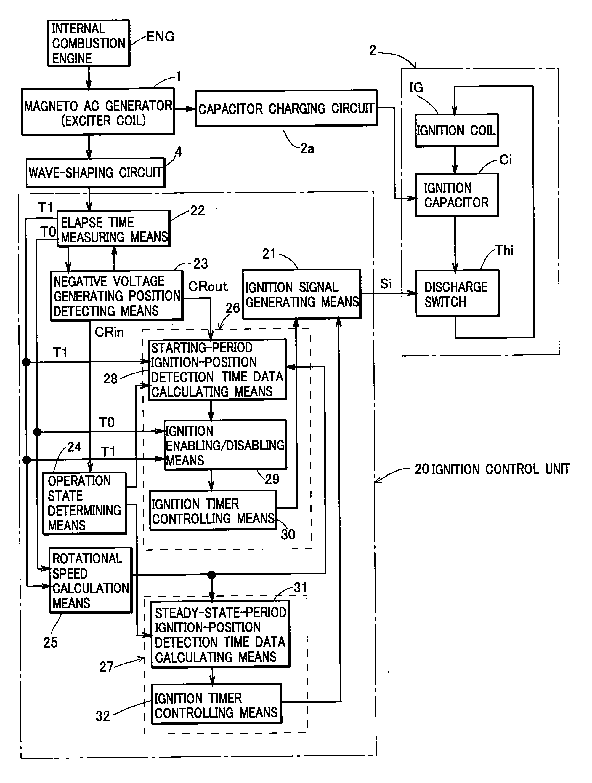
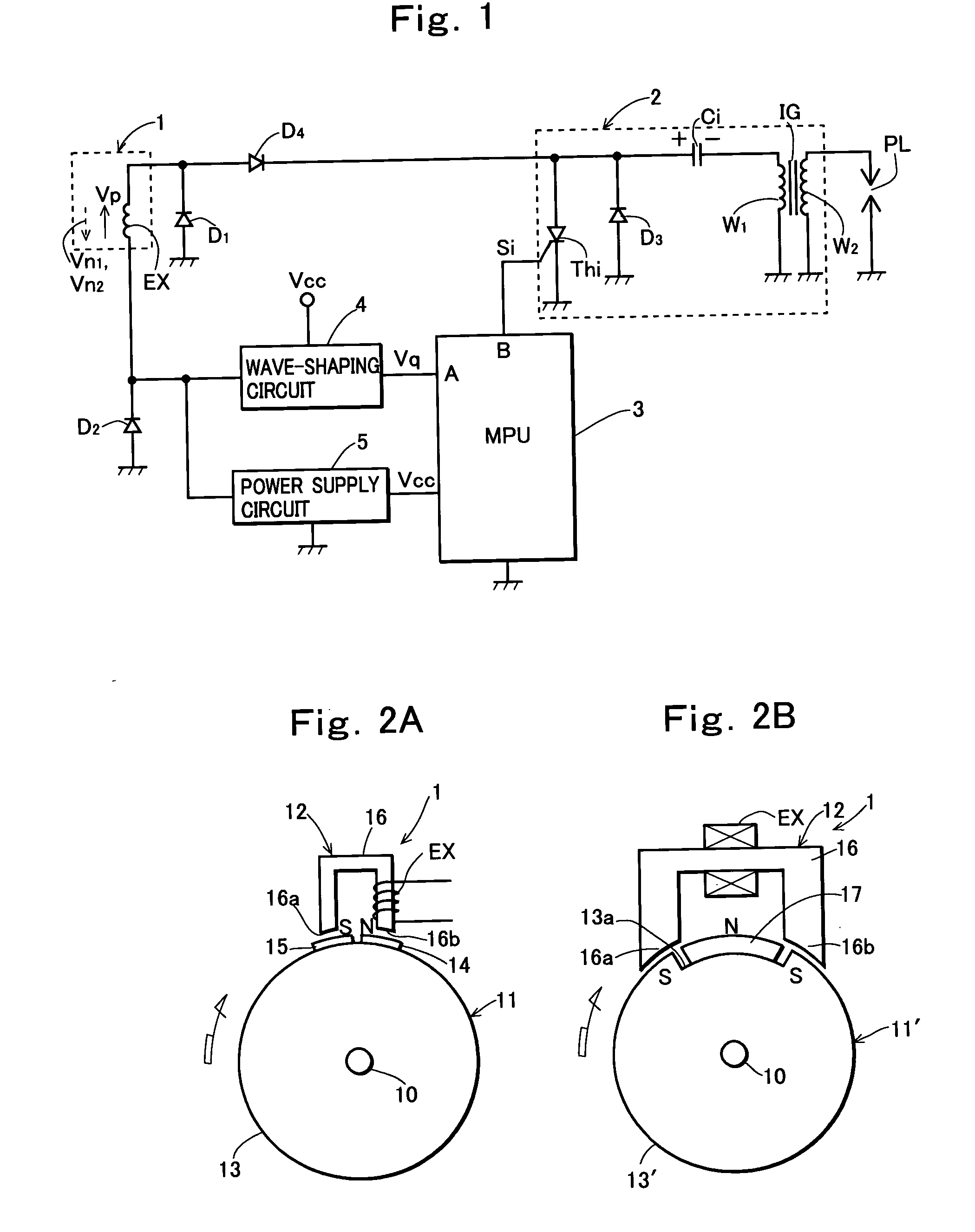
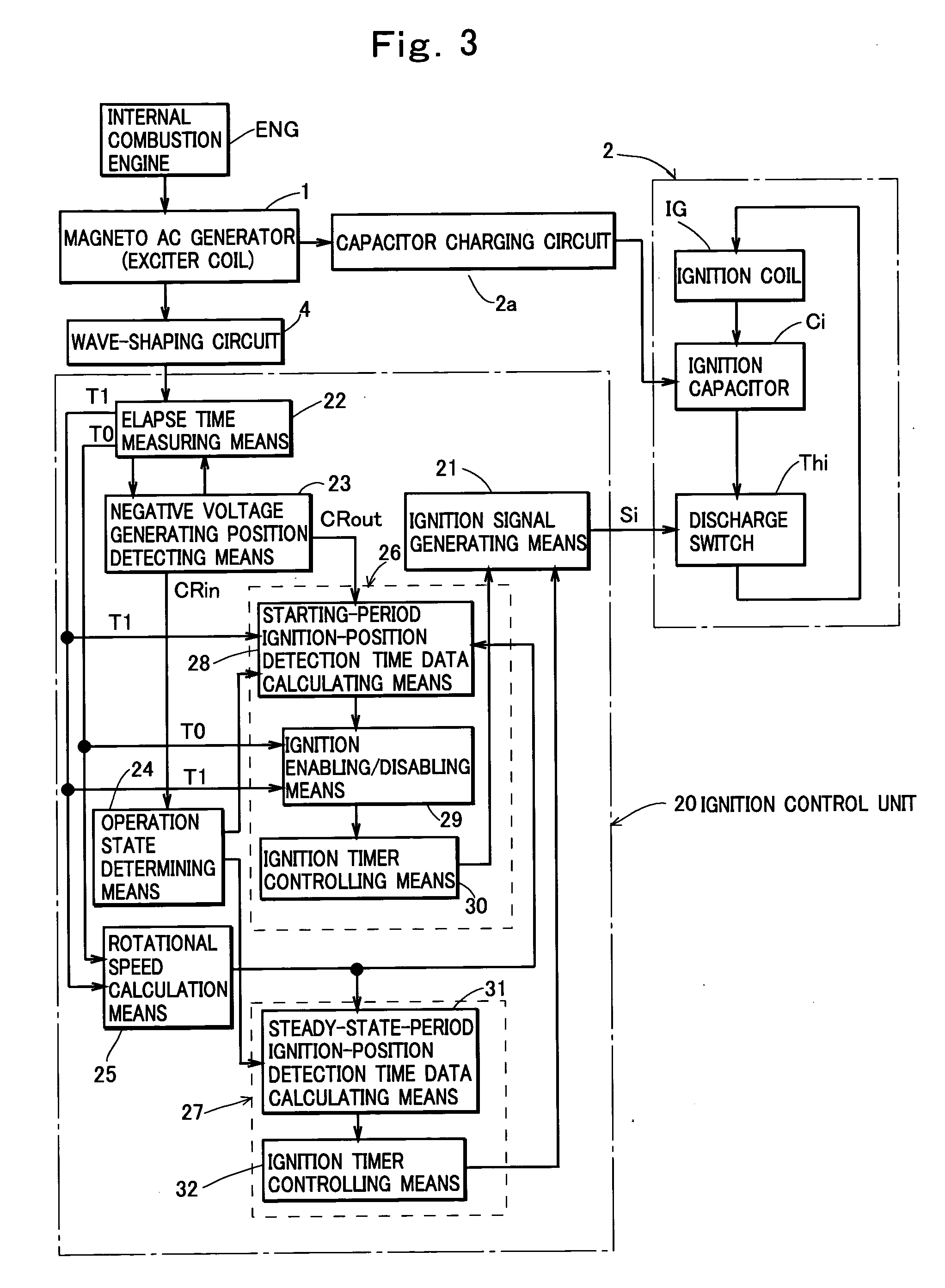
[0068]FIG. 1 schematically shows a hardware construction of this embodiment, in which a reference numeral 1 denotes a magneto generator driven by an internal combustion engine (not shown); 2 denotes a capacitor-discharge-type ignition circuit; 3 denotes a microprocessor; 4 denotes a wave-shaping circuit; and 5 denotes a power supply circuit for supplying power supply voltage Vcc to the microprocessor 3 and the wave-shaping circuit 4.

[0069] The magneto AC generator 1 used in this embodiment has a construction as shown in FIG. 2A. The magneto AC generator 1 shown in FIG. 2A comprises a magnetic rotor 11 mounted to a crankshaft 10 of the internal combustion engine (not shown), and a stator 12. The magnetic rotor 11 comprises a flywheel 13 of aluminum mounted to the crankshaft 10, permanent magnets 14 and 15 that are cast into the flywheel 13 with the magnets being magnetized in radial d...


PUM


Abstract

A capacitor-discharge-type ignition device for an internal combustion engine, comprising: an exciter coil that generates an AC voltage having a positive half-wave voltage and first and second negative half-wave voltages present before and after the positive half-wave voltage synchronously with rotation of the engine; ignition-position detection time data calculating means that arithmetically operates as ignition position detection time data, the time period that is required for the engine to rotate from the generating position of the second negative half-wave voltage to an ignition position suitable in starting period, at the rotational speed of the engine that is obtained from time period from generation of the first negative half-wave voltage to the generation of the second negative half-wave voltage, and from an angle between the generating position of the first negative half-wave voltage and that of the second negative half-wave voltage, wherein a crank angle position when the measurement of the arithmetically operated ignition position detection time data is completed is determined as an ignition position at a low speed operation of the engine.

Description

TECHNICAL FIELD OF THE INVENTION [0001] The present invention relates to a capacitor-discharge-type ignition device for an internal combustion engine. BACKGROUND OF THE INVENTION [0002] A capacitor-discharge-type ignition device for an internal combustion engine comprises an ignition coil, an ignition capacitor provided in a primary side of the ignition coil and charged in one polarity by an output of an ignition power supply, a discharge switch which becomes a conducting state when receiving an ignition signal and causes electrical charges stored in the ignition capacitor to be discharged through the primary coil of the ignition coil, and an ignition control unit for supplying the ignition signal to the discharge switch at an ignition timing of the internal combustion engine. As the ignition power supply, exciter coils provided in magneto AC generators mounted to engines are often used. [0003] For current vehicles driven by internal combustion engines and apparatuses driven by inte...

Claims


Application Information

Patent Timeline
IPC IPC(8): F02P5/15
CPCF02P1/086F02P3/0869F02P5/1506Y02T10/46Y02T10/40
Inventor SHIMOYAMA, AKIRANAKAUCHI, KIYOTADAHATANO, YASUKAZUSUGIYAMA, MASAYUKI
Owner MAHLE INT GMBH
Why Eureka
Try Eureka