Cooling structure of heat generating member

a technology of heat generating member and cooling structure, which is applied in the control arrangement of battery/fuel cell, electric devices, electrochemical generators, etc., can solve the problem of increasing the size of the battery system

Inactive Publication Date: 2006-08-03
DENSO CORP
View PDF10 Cites 77 Cited by
  • Summary
  • Abstract
  • Description
  • Claims
  • Application Information

AI Technical Summary

Benefits of technology

[0005] In view of the above-described problems, it is an object of the present invention to provide a cooling

Problems solved by technology

Furthermore, various equipments having different sizes are simply locate

Method used


Image

  • Cooling structure of heat generating member
  • Cooling structure of heat generating member
  • Cooling structure of heat generating member

Examples


first embodiment

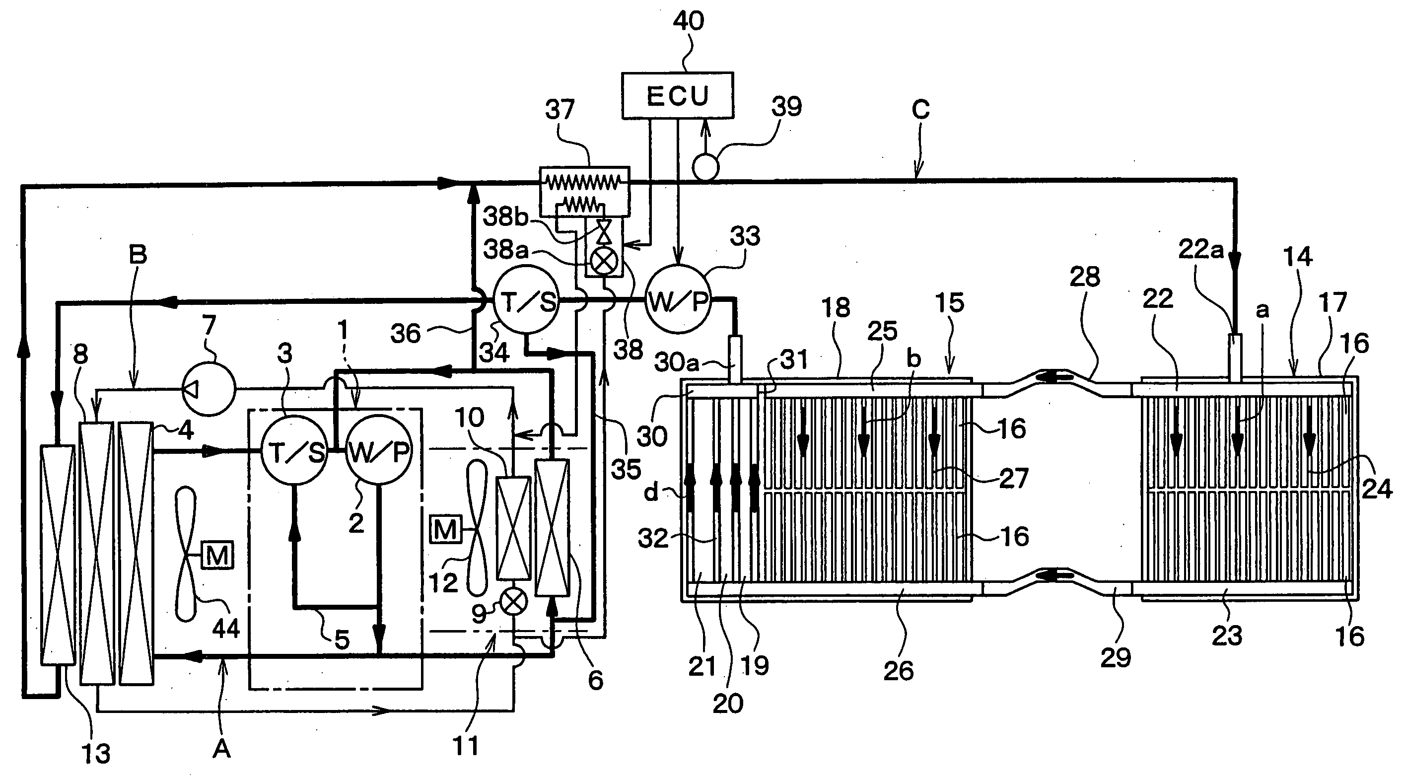
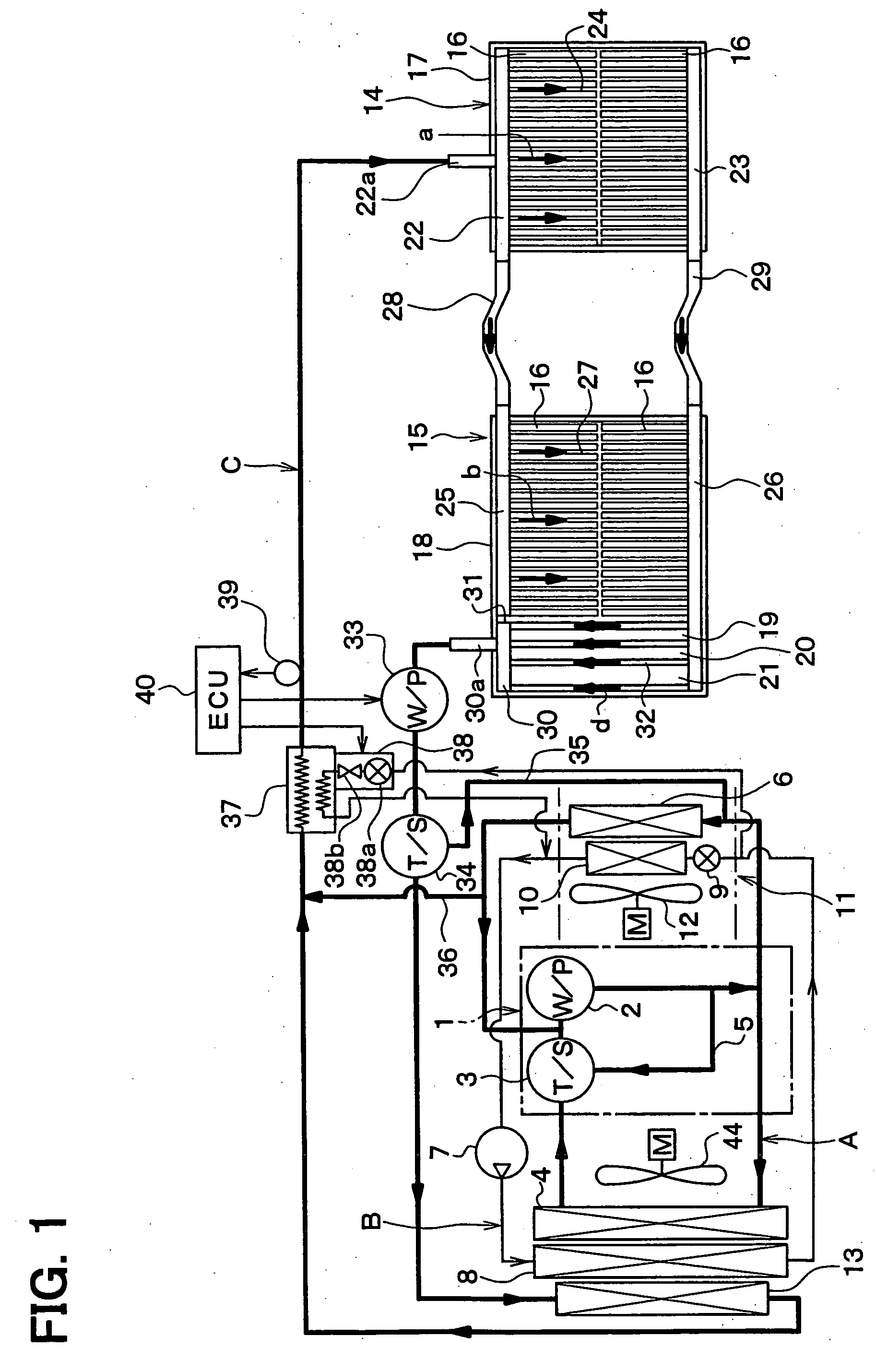
[0037]FIG. 1 shows a schematic diagram showing an entire system of the first embodiment. In this embodiment, the present invention is typically applied to a hybrid vehicle which is driven by an engine (internal combustion engine) 1 and an electrical motor (not shown) as driving sources.

[0038] The system of the first embodiment is constructed with a cooling water circuit A of an engine 1, a refrigerant cycle B for a vehicle air conditioner, a cooling water circuit C for heat generating members.

[0039] The cooling water circuit A of the engine 1 has a structure generally known. A water pump 2 driven and rotated by the engine 1 is located in the cooling water circuit A so as to circulate cooling water in the cooling water circuit A by the operation of the water pump 2.

[0040] A thermostat 3 is arranged at a suction side of the water pump 2, and is used as a thermal responding valve operated in accordance with a cooling water temperature. A radiator 4 and a bypass passage 5 are arrange...

second embodiment

[0095] The second embodiment of the present invention will be now described with reference to FIG. 4. In the second embodiment, a spring member 61 is located inside the case 18 so as to accurately press-contact each of the heat generating members (e.g., battery parts 16, DC voltage converters 19, 20, electrical member 21) and the heat exchanging plate member 51, 52. The cooling structure of the second embodiment is described by using the second cooling unit 15 described in the first embodiment. Furthermore, the parts of the second cooling unit 15 of FIG. 4, similar to those of the first embodiment, are indicated as the same reference numbers, and detail description thereof is omitted.

[0096] The spring member 61 is formed from a metal spring material, and is formed into a plate shape. As shown in FIG. 4, the spring member 61 is located between an inner wall surface of one end of the case 18 and one end portion of the heat exchanging plate members 51, 52 in the laminating direction. ...

third embodiment

[0100]FIG. 5 shows the third embodiment that is a modification of the above-described second embodiment. In the third embodiment, the DC voltage converters 19, 20 are arranged in parallel on the side of the outlet passage portion 30 partitioned from the inlet passage portion 25, so that each of the DC voltage converters 19, 20 is cooled from both sides. In contrast, the electrical member 21 of the second embodiment is provided outside of the case 18. In the third embodiment, the other parts can be made similar to those of the above-described second embodiment.


PUM


Abstract

A cooling structure includes a plurality of plate-shaped heat generating members such as battery parts, DC voltage converters and electrical member (e.g., relay). In the cooling structure, the heat generating members are arranged in a plate-thickness direction to have predetermined spaces for forming fluid passages each of which is provided between adjacent heat generating members, and the fluid passages are provided to pass a fluid for cooling the heat generating members. Accordingly, all the heat generating members can be effectively cooled while the cooling structure can be made compact.

Description

CROSS REFERENCE TO RELATED APPLICATION [0001] This application is based on Japanese Patent Application No. 2005-26443 filed on Feb. 2, 2005, the contents of which are incorporated herein by reference in its entirety. FIELD OF THE INVENTION [0002] The present invention relates to a cooling structure, which effectively and collectively cools plural heat generating members. BACKGROUND OF THE INVENTION [0003] In a battery system for an electrical vehicle described in JP-A-2002-84604, a cooling fan of a battery is provided to cool an electrical part and an electronic control unit. Specifically, the cooling fan is provided in a cool air passage for cooling the battery, and an electrical detector and the electronic control unit are arranged in the cool air passage to be cooled by air blown from the cooling fan. Here, the electrical detector is disposed for detecting a battery charge / discharge current, and the electronic control unit has a microcomputer for calculating a battery remaining c...

Claims


Application Information

Patent Timeline
IPC IPC(8): B60K11/04B60K1/04H01M10/60B60L15/00H01M10/613H01M10/625H01M10/633H01M10/647H01M10/651H01M10/653H01M10/6553H01M10/6563H01M10/6565H01M10/6568H01M10/6569
CPCB60K11/02Y02T10/70B60K2001/005F01P7/165F01P2005/105F01P2050/24F01P2060/08F01P2060/14H01M10/5004H01M10/5006H01M10/5016H01M10/502H01M10/5032H01M10/5059H01M10/5067H01M10/5077H01M10/5079H01M10/5095H01M10/5097B60L1/003B60L1/02B60L3/0023B60L3/0046B60L11/1864B60L11/1874B60L11/1875B60L11/1877B60L11/1879B60L2240/34B60L2240/36B60L2240/445B60L2240/545B60L2240/662B60L2210/10B60L3/003B60L11/14Y02T10/7077Y02T10/7005Y02T90/16Y02T10/7061Y02T10/7216Y02T10/7291B60K2001/003H01M10/625H01M10/63H01M10/615H01M10/663H01M10/6563H01M10/647H01M10/6568H01M10/6569H01M10/6557H01M10/667H01M10/613B60L50/16B60L58/21B60L58/26B60L58/27B60L50/66B60L50/64B60L58/18Y02T10/72Y02T10/7072Y02E60/10
Inventor INOUE, YOSHIMITSUMAKIHARA, MASAMICHIYAMANAKA, TAKASHI
Owner DENSO CORP
Why Eureka
Try Eureka