Solenoid Valves

a solenoid valve and valve body technology, applied in the direction of valve details, valve arrangement, operating means/releasing devices, etc., can solve the problems of increased cost, increased dimensional accuracy, and inability to obtain or maintain initial expected flow rate, so as to achieve precise dimensional accuracy in valve components and precise assembling the effect of valv

Inactive Publication Date: 2006-08-03
NONAKA TAKUMI +2
View PDF5 Cites 17 Cited by
  • Summary
  • Abstract
  • Description
  • Claims
  • Application Information

AI Technical Summary

Benefits of technology

[0010] In order to solve the problems described above, a solenoid valve is provided comprising:
[0011] a drive portion comprising a bobbin comprising a slidable hole formed therethrough, a fixed iron core disposed in the slidable hole and a movable iron core slidably disposed within the slidable hole; and
[0012] a valve function portion comprising a valve body extending from the movable iron core and disposed in a leading end of a valve shaft passing through the fixed iron core and a valve seat with which the valve body is brought into close contact and from which the valve body is separated,
[0013] wherein a magnitude of a gap formed between the valve body and the valve seat is adjustable when the valve is opened, by means of a flow rate adjusting screw, which may be adjusted from an outer side in a rear end of the solenoid valve and comprises a leading end protruding into the slidable hole to bring the leading end into contact with a rear end surface of the movable iron core when the valve is opened, thereby adjusting a protrusion amount of the screw into the leading end of the slidable hole.
[0014] Accordingly, a valve stroke width may be adjusted precisely without requiring a precise dimensional accuracy in valve components and a precise accuracy in assembling the valve, and even when a width of an original gap formed between the valve body and the valve seat may become excessive due to use and may generate a flow rate, it is possible to return to the initial gap width only by turning the flow rate adjusting screw.
[0015] On the other hand, a solenoid valve may be provide, comprising:

Problems solved by technology

In the solenoid valve used for controlling the fluid flows as described above, a magnitude (e.g., a width) of a valve stroke generally is limited, a width of a gap formed between a valve body and a valve seat and constituting a flow path may become excessive due to a slight variation part dimensions and a slight inaccuracies at the time of assembling, or a change in width may occur due to a long-term use, whereby an initially expected flow rate may not be obtained or maintained.
H05-18473, the temporary spacer must be attached and detached when assembling the valve, and the number of assembly steps is increased, resulting in a cost increase.
Further, among both of these configurations, when the width of the gap formed by the valve seat and the valve body is changed through use of the solenoid valve over a long term, and the flow rate is changed to a different flow rate from the original or initial flow rate when the valve was opened, it is difficult to adjust to this situation.

Method used


Image

  • Solenoid Valves
  • Solenoid Valves
  • Solenoid Valves

Examples


first embodiment

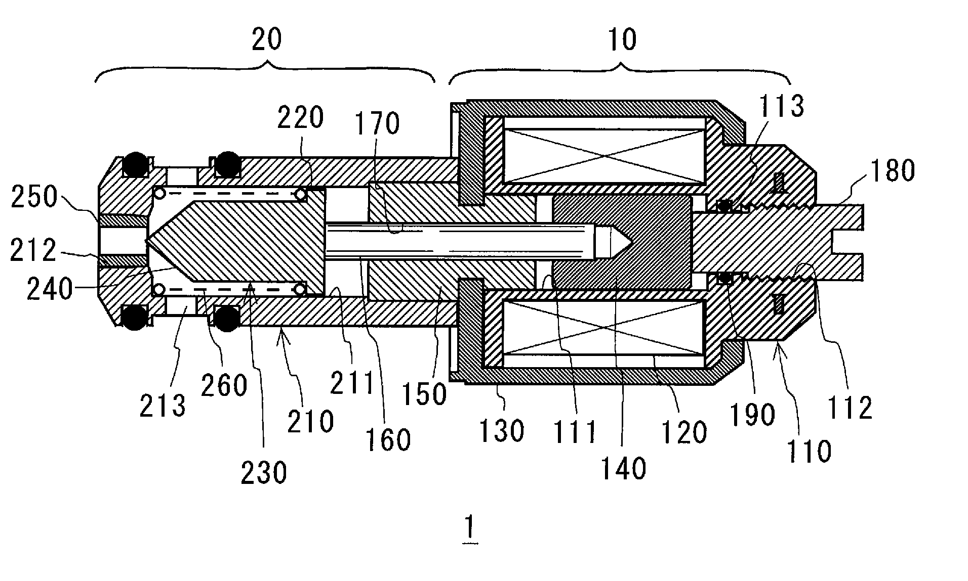
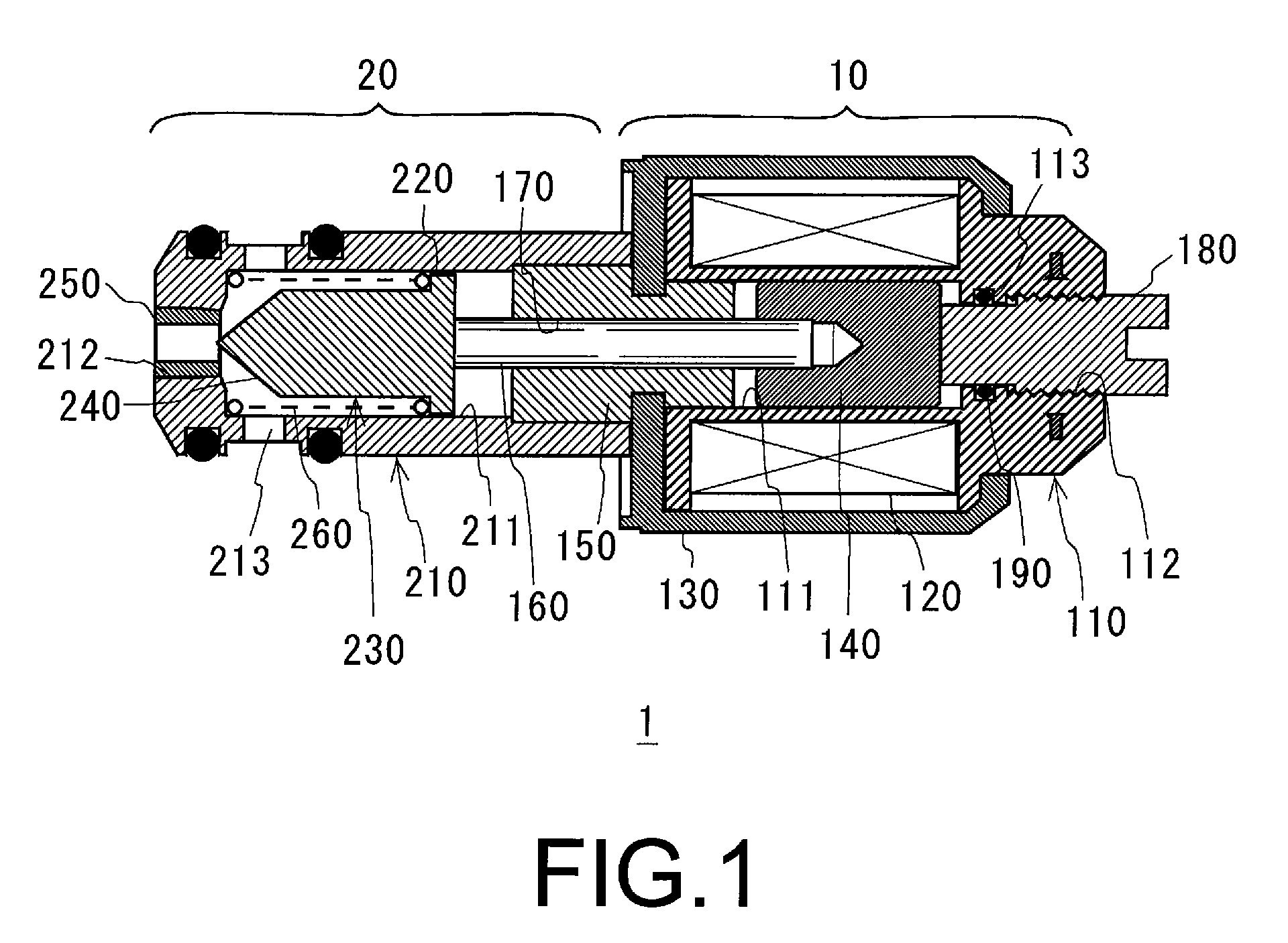
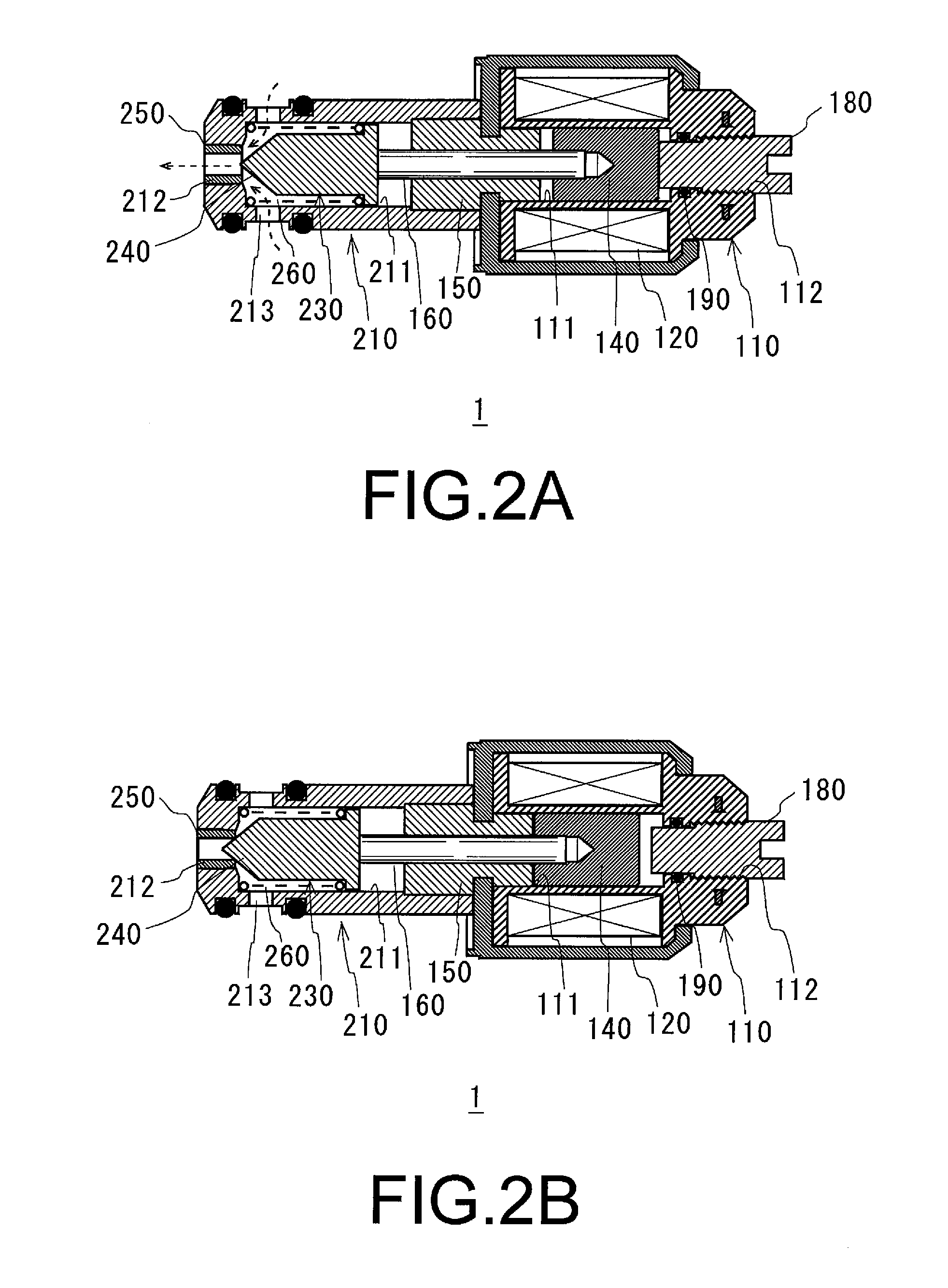
[0034] FIGS. 1 to 3 show cross-sectional views of a normally open-type, solenoid valve 1 corresponding to a first embodiment in the present invention. Normally open-type, solenoid valve 1 may be disposed in a fuel supply, pipe path of an engine and may be used as a fluid control valve for a supplied fuel. A right side portion in FIG. 1 depicts a drive portion 10, and a left side portion depicts a valve function portion 20.

[0035] Drive portion 10 comprises a slidable hole 111 formed through the center, and comprises an electric conduction coil 120 formed by winding an electric conduction line or wire around an outer periphery of a bobbin 110 corresponding to a main body portion of solenoid valve 1. Electric conduction coil 120 is configured to excite in response to a current, such as a battery current, applied via wiring (not shown). Further, an outer side of bobbin 110 is provided with a cover body 130 covering bobbin 110 and sealing an inner portion of bobbin 110. An substantially ...

second embodiment

[0045]FIG. 4 shows a cross-sectional view of a solenoid valve 2 obtained by applying the present invention to a normally closed-type solenoid valve, in accordance with the present invention. A difference between solenoid valve 1 and solenoid valve 2 is that in solenoid valve 2, a needle 231 is urged in a valve closing or leading direction by spring 260 to close solenoid valve 2 when solenoid valve 2 is not energized. A movable iron core 141 is drawn by a magnetic force of a fixed iron core 151 disposed in a rear end side, when solenoid valve 2 is energized, so as to be urged rearward and to open the valve. Further, when a leading end surface of flow rate adjusting screw 180 approaches an open end of a through hole 171 as it moves through hole 171 of fixed iron core 151, and screw 180 is brought into contact with the end surface of convex portion 270 protruding to a rear end side of movable iron core 151 when solenoid valve 2 is opened, the size or width of the gap formed between val...


PUM


Abstract

In a solenoid valve, a desire valve stroke width may be set, and a flow rate may be returned to an original flow rate even when that the flow rate is changed. A solenoid valve includes a drive portion having a bobbin including a slidable hole formed there through, a fixed iron core disposed with in the bobbin and a movable iron core disposed to be slidable within the slidable hole, and a valve function portion having a valve body extending from the movable iron core and disposed in a leading end of a valve shaft passing through the fixed iron core and a valve seat with which the valve body is brought into close contact and from which the valve body is separated. In the solenoid valve, a predetermined gap width is formed between the valve body and the valve seat, when the solenoid valve is not energized, to open the valve, and the movable iron core is drawn to the fixed iron core when the solenoid valve is energized to close the valve. A valve stroke width may be adjusted by screwing a flow rate adjusting screw from an outer side in a rear end of the solenoid valve to bring the leading end into contact with a rear end surface of the movable iron core when the valve is opened, thereby adjusting a protrusion amount of the screw in the leading end of the slidable hole.

Description

BACKGROUND OF THE INVENTION [0001] 1. Field of the Invention [0002] The present invention relates to solenoid valves which control a fluid flow by opening and closing a valve in response to the application of a current. [0003] 2. Description of Related Art [0004] A normally closed-type, solenoid valve (e.g., an electromagnetic valve), which is opened in response to the attraction of a movable iron core (e.g., an armature) to a fixed iron core (e.g., a core) magnetized by the application of a current to a surrounding coil, is frequently used as a valve for controlling the opening and the closing of a fuel supply, pipe line and a working fluid, supply path of a vehicle. On the other hand, a normally open-type, solenoid valve which is normally opened and is closed when electricity is applied, also is known, for example, as described in Japanese Unexamined Patent Publication No. H09-229229. The normally open-type, solenoid valve has an advantage that a flow rate may be maintained and th...

Claims


Application Information

Patent Timeline
Patent Type & Authority Applications(United States)
IPC IPC(8): F16K31/02
CPCF16K31/0655F16K31/0675
Inventor NONAKA, TAKUMIIWAANA, MITSUHIROWATANABE, HIDEKI
Owner NONAKA TAKUMI
Why Eureka
Try Eureka