Rotor and process for manufacturing the same

a technology of rotating parts and rotors, applied in the field of rotating parts, can solve the problems of lowering the efficiency of motors, undesirable magnetic fluxes, and unsuitable high-speed rotation motors, and achieves high degree of freedom, high press-bonding strength, and effective use of magnetic forces.

Inactive Publication Date: 2006-08-03
HITACHI METALS LTD
View PDF26 Cites 51 Cited by
  • Summary
  • Abstract
  • Description
  • Claims
  • Application Information

AI Technical Summary

Benefits of technology

[0015] Accordingly, an object of the present invention is to provide a permanent magnet-embedded rotor free from gaps between permanent magnets and a soft magnetic material and cracking due to springback, capable of...

Problems solved by technology

The magnetic fluxes B1, B2 are undesirable because they eat the magnetic flux contributing to the torque of a motor.
Accordingly, such motors are not suitable for high-speed rotation.
This clearance acts as an air gap in a magnetic circuit, thereby lowering the efficiency of motors.
Further, the clearance deteriorates the positional accuracy of the permanent magnets, resulting in uneven magnetic pole pitches and thus a cogging torque.
Accordingly, it is difficult to produce extremely thin portions of the permanent magnets and the silicon steel sheets with high accuracy.
However, this method is applicable only to the SPM motors, failing to solve the production problems of the magnet-embedded motors.
A magnet-embedded rotor needs bridging soft magnetic portions for avoiding impact and for reinforcement between pluralities of permanent magnets, but these portions permit the short-circuiting of a magnetic flux generated by the permanent magnets, resulting in a leaked magnetic ...

Method used


Image

  • Rotor and process for manufacturing the same
  • Rotor and process for manufacturing the same
  • Rotor and process for manufacturing the same

Examples


example 2

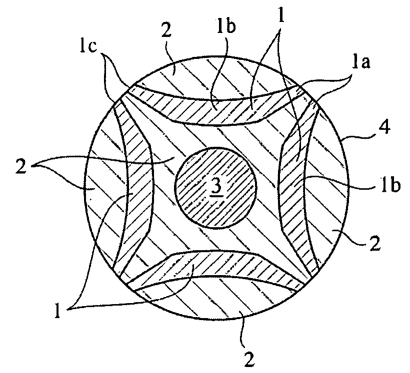
[0107] In a rotor shown in FIG. 2(a), in which the end surfaces 1c of bonded magnet portions 1 were not exposed to a peripheral side surface 4, the thinnest portions 2a of the soft magnetic portion 2 between the end surfaces 1c of the bonded magnet portions 1 and the peripheral side surface 4 being as thin as 0.3 mm, a tensile stress was 19 MPa in the thinnest portions 2a, to which the largest tensile stress was applied. Though it was expected that a residual stress were relaxed in the rotor of Comparative Examples 1 and 2 shown in FIGS. 10 and 12, in which the soft magnetic portion 2 was divided by the bonded magnet portions 1 to inner and outer portions, outer soft magnetic portions 2 being freely expandable, it was found that cracking was actually suppressed more in the rotor having the shape shown in FIG. 2(a).

[0108]FIG. 13 shows the relation between the thickness of the thinnest portion 2a and a maximum residual stress in that portion. In a rotor design having a residual stres...

example 3

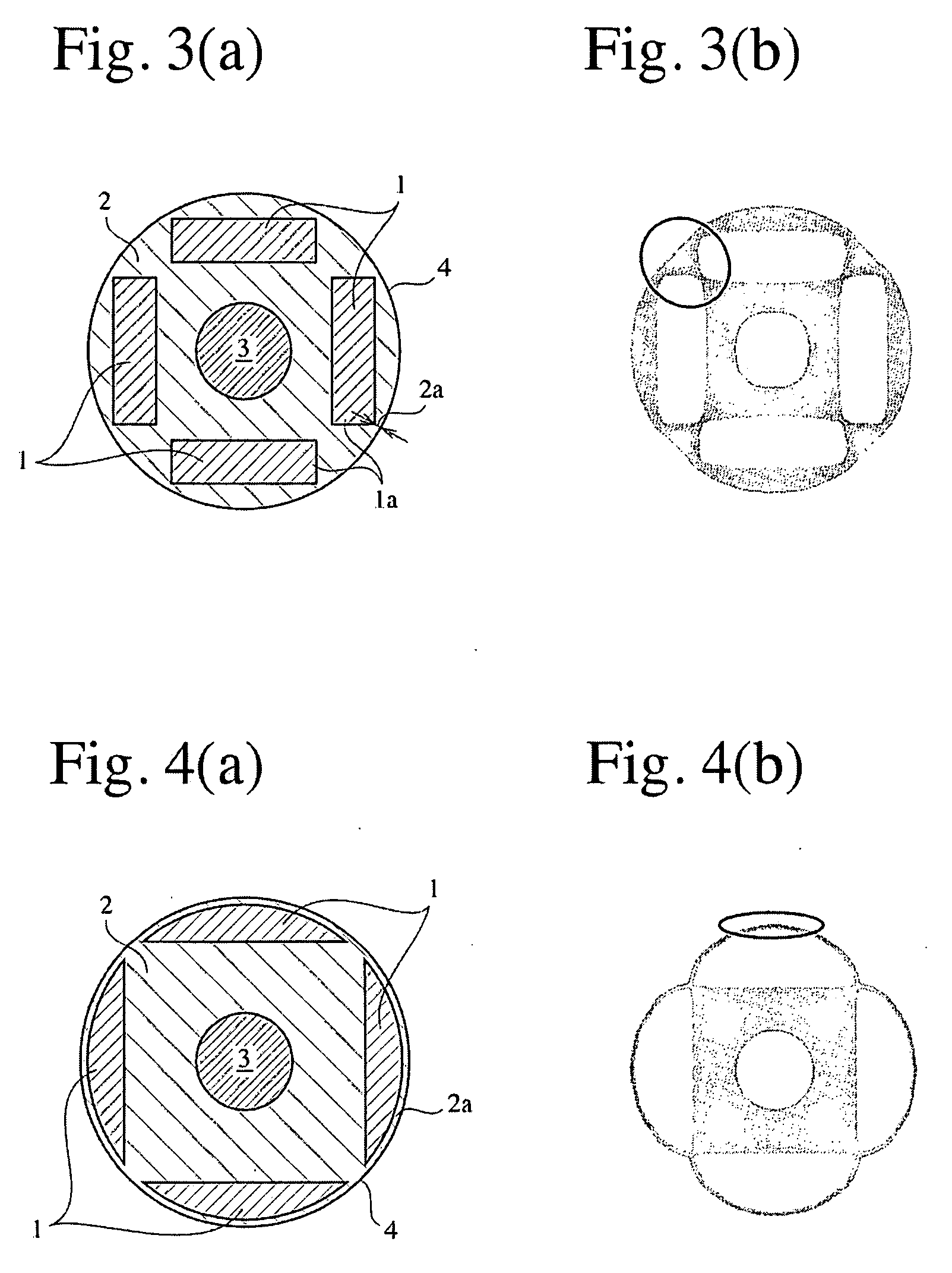
[0109]FIG. 3(a) shows a rotor comprising bonded magnet portions 1 each having a rectangular axial cross section embedded in a soft magnetic portion 2 with gaps between their ends 1a, 1a. The rotor had an outer diameter of 50 mm, and each bonded magnet portion 1 had a thickness of 5 mm, and a transverse width of 25 mm. The thinnest portions 2a of the soft magnetic portion 2 had a thickness of 1.3 mm. FIG. 3(b) shows a tensile stress distribution in the rotor shown in FIG. 3(a) when it was deformed. The largest tensile stress was applied to the thinnest portions 2a of the yoke, where the tensile stress was 11 MPa.

[0110] It was found by analysis that this rotor had substantially the same relation between the thinnest portions 2a and the maximum residual stress in the thinnest portions 2a as shown in FIG. 13, despite slight difference. Stress analysis with changed thickness of the bonded magnet portions provided the same results.

example 4

[0111]FIG. 4(a) shows a rotor comprising bonded magnet portions 1 totally embedded in a soft magnetic portion 2, each bonded magnet portion 1 having a cross section shape having an arcuate side extending along a periphery of the rotor and a linear bottom. The rotor had an outer diameter of 50 mm, and the bonded magnet portion 1 had the maximum width of 7 mm, and a bottom length of 35 mm. The soft magnetic portion 2 had a thin portion 2a having a thickness of 1 mm outside the bonded magnet portions 1. FIG. 4(b) shows a tensile stress distribution in the rotor of FIG. 4(a) when it was deformed. The largest tensile stress was applied to the thin portion 2a of the soft magnetic portion 2, where the tensile stress was 11 MPa.

[0112] It was by analysis found that this rotor had substantially the same relation between the thin portion 2a and the maximum residual stress therein as shown in FIG. 13, despite slight difference. Stress analysis with changed thickness of the bonded magnet portio...


PUM

PropertyMeasurementUnit
Lengthaaaaaaaaaa
Lengthaaaaaaaaaa
Fractionaaaaaaaaaa

Abstract

A rotor comprising bonded magnet portions mainly composed of magnet powder and a binder, which are embedded in a soft magnetic portion mainly composed of soft magnetic powder and a binder, the rotor being produced by a compression-molding method, and the magnetic pole surfaces of the bonded magnet portions being embedded in the soft magnetic portion.

Description

FIELD OF THE INVENTION [0001] The present invention relates to a rotor integrally comprising permanent magnets and a yoke suitable for high-efficiency motors, generators, etc. BACKGROUND OF THE INVENTION [0002] As permanent magnet motors, there are surface permanent magnet (SPM) motors comprising permanent magnets on peripheral portions of rotors, and interior permanent magnet (IPM) motors comprising permanent magnets embedded in rotors, etc. [0003] As shown in FIG. 16, the SPM motor has a structure in which permanent magnets 31 on a rotor surface are in direct contact with an air gap 34 between the rotor and a stator 33 comprising a yoke 32 and coils 37. The magnetic circuit shown in FIG. 16 is generally called a surface-magnet-type magnetic circuit. A magnetic flux A1 emanating from an N pole of a permanent magnet 31a penetrates the air gap 34, passes through portions 33a, 33b and 33c of the stator yoke 33, and penetrates the air gap 34 again, passes through a permanent magnet 31b...

Claims


Application Information

Patent Timeline
IPC IPC(8): H02K21/12H02K1/27H02K15/03
CPCH02K1/276Y10T29/49012H02K15/03H02K1/2766
Inventor MASUZAWA, MASAHIROTANIGAWA, SHIGEHOMITA, MASAHIROKIKUCHI, KEIKO
Owner HITACHI METALS LTD
Why Eureka
Try Eureka