Linear motor force ripple identification and compensation with iterative learning control

a technology of linear motor and learning control, applied in the direction of program control, dynamo-electric converter control, instruments, etc., can solve the problems of alignment errors, slight delay between current and follow-up error of wafer stage and/or reticle stage, etc., to achieve high acceleration, high speed, and high accuracy of lithography system

Inactive Publication Date: 2006-08-03
NIKON CORP
View PDF11 Cites 25 Cited by
  • Summary
  • Abstract
  • Description
  • Claims
  • Application Information

AI Technical Summary

Benefits of technology

[0010] Embodiments of the present invention are directed to compensating for force ripple of an apparatus driven by a force produced by a linear motor. More particularly, the force ripple compensation is used in conjunction with iterative learning control to render the control method simpler, more effective, and more robust. Accurate control of the motion of mechanical stages may be achieved to meet the demands of high acceleration, high speed, and high accuracy of lithography systems or the like.

Problems solved by technology

Unfortunately, during the movement of the stages, a following error of the wafer stage and / or the reticle stage can occur.
For example, the following error can occur due to a lack of complete rigidity in the components of the exposure apparatus, which can result in a slight time delay between current being directed to the mover assembly and subsequent movement of the stage.
Additionally, alignment errors can occur even if the stages are properly positioned relative to each other.
For example, periodic vibration disturbances of various mechanical structures of the exposure apparatus may occur.
More specifically, oscillation or resonance of the optical assembly and / or other supporting structures can inhibit relative alignment between the stages and the optical assembly.
As a result of the following errors and / or the vibration disturbances, precision in the manufacture of the semiconductor wafers can be compromised, potentially leading to production of a lesser quality semiconductor wafer.
Unfortunately, this method is not entirely satisfactory and the control system does not always precisely move each stage along its intended trajectory.

Method used


Image

  • Linear motor force ripple identification and compensation with iterative learning control
  • Linear motor force ripple identification and compensation with iterative learning control
  • Linear motor force ripple identification and compensation with iterative learning control

Examples


Embodiment Construction

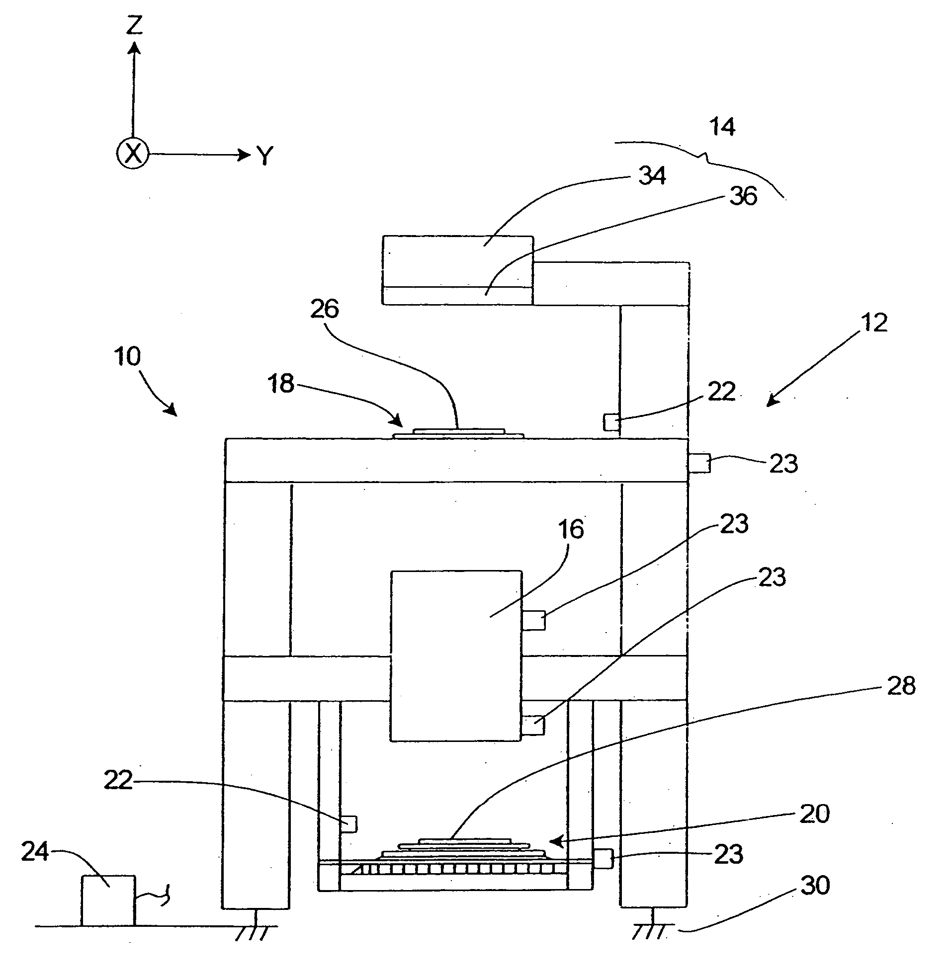
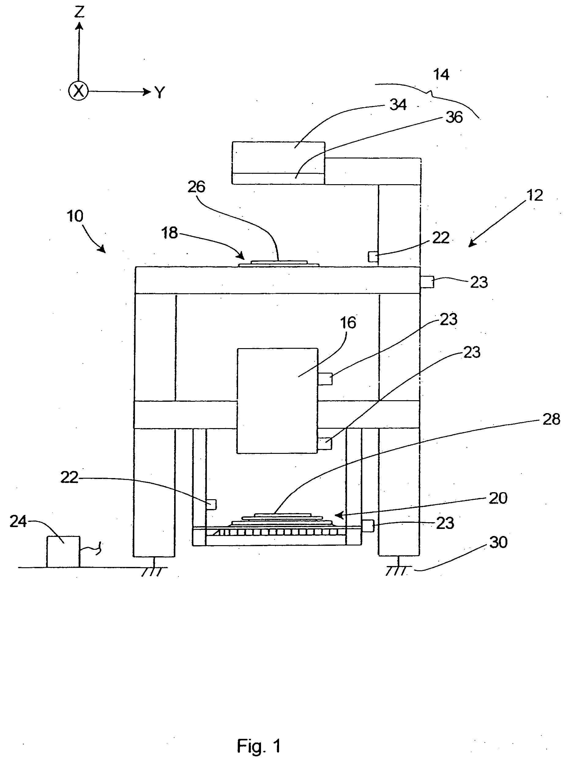
[0053] Lithography systems demand high acceleration, high speed and extreme accuracy on the motion of mechanical stages. Conventional following error driven feedback controls such as PID alone cannot meet the performance requirement due to the closed-loop bandwidth limitations from the mechanical resonance modes and electrical amplifiers. Although the system performance may be enhanced by feedforward control and feedback linearization, the models may not be accurate enough to meet the performance specification due to the system complexity. Due to the repetitive pattern of the step-scan-and-repeat of wafer stage motions, ILC may serve as the final resort to compensate all the repetitive residual following errors to ensure excellent settling time and accuracy.

[0054] Iterative learning control (ILC) has been intensely studied and applied to many control systems with repetitive motions. In contrast to the general compensations, based on the information of previous time steps, the ILC i...


PUM


Abstract

Embodiments of the present invention are directed to compensating for force ripple of an apparatus driven by a force produced by a linear motor. In one embodiment, a method of compensating for force ripple comprises generating force commands for a trajectory starting at a plurality of starting positions of the apparatus driven by the linear motor to produce different trajectory motions based on the same trajectory at the plurality of starting positions, the force commands each including peaks of large acceleration/deceleration and valleys of low force levels; calculating an average of the force commands during large acceleration/deceleration generated based on trajectory motions for the plurality of starting positions; calculating a variation ratio of the force command for each trajectory motion to the calculated average of the force commands; and compensating for force ripple in the apparatus based on the calculated variation ratio to control the force applied by the linear motor to the apparatus.

Description

CROSS-REFERENCES TO RELATED APPLICATIONS [0001] Not Applicable BACKGROUND OF THE INVENTION [0002] The present invention relates generally to a control system and method for controlling the trajectory and alignment of one or more stages in a semiconductor wafer exposure system and, more particularly, to reducing following error in the iterative learning control (ILC) methodology by compensating for force ripple. [0003] An exposure apparatus is one type of precision assembly that is commonly used to transfer images from a reticle onto a semiconductor wafer during semiconductor processing. A typical exposure apparatus includes an illumination source, a reticle stage assembly that retains a reticle, an optical assembly, a wafer stage assembly that retains a semiconductor wafer, a measurement system, and a control system. [0004] In one embodiment, the wafer stage assembly includes a wafer stage that retains the wafer, and a wafer mover assembly that precisely positions the wafer stage an...

Claims


Application Information

Patent Timeline
Patent Type & Authority Applications(United States)
IPC IPC(8): H02K33/00H02K41/00
CPCG03F7/70725G03F7/70758G05B19/258G05B2219/41132G05B2219/41209G05B2219/41337G05B2219/42065G05B2219/42141G05B2219/45031H02P1/16H02P23/02H02P23/04H02P25/06
Inventor YANG, PAI-HSUEHHASHIMOTO, HIDEYUKIYUAN, BAUSANYAMAGUCHI, ATSUSHI
Owner NIKON CORP
Why Eureka
Try Eureka