Tool storage case

a tool and storage case technology, applied in the field of tool storage cases, can solve the problems of inconvenient transportation of audio devices by transportation vehicles to work sites, inability to work while talking to each other, and inability to separate or contact batteries, so as to prevent the body and other electric devices from being stolen, and the effect of generating dust and impa

Inactive Publication Date: 2006-08-03
HITACHI KOKI CO LTD
View PDF23 Cites 26 Cited by
  • Summary
  • Abstract
  • Description
  • Claims
  • Application Information

AI Technical Summary

Benefits of technology

[0046] Since the power cord is composed of a winding type cord, which is wound by a helical spring, the invention has further another advantage that the power cord is not held by obstacles and not obstructed when being stored in the tool storage case.
[0047] When the cover case the tool storage case is open, storage partition walls in which the inner wiring lines are disposed are formed by double walls so that the inner wiring lines in the tool storage case is not exposed. Then, the inner wiring lines are disposed between the double walls. Furthermore, the double walls are covered with an elastic member, such as rubber, serving as a lid. Accordingly, the invention has another advantage that the inner wiring lines are not exposed and thus can be protected from damages.
[0048] An engaging mechanism (latching mechanism) between the storage case and the battery pack is the same as the engaging mechanism of the battery pack for engaging the battery pack w

Problems solved by technology

For example, when one or more workers work in the construction site of a general house or building, they cannot work while talking to each other.
Accordingly, it is difficult to pack the audio devices in a compact manner to transport them together with the electric tool.
Furthermore, it is inconvenient to transport the audio devices by a transportation vehicle to the work site, and to carry the audio devices in the work site.
In addition, when other electric devices or working devices are also transported, it takes time and effort to transport the devices over several trips.
Moreover, since there is much noise of other electric tools, construction vehicles, or generators in the work site, it is required that th

Method used


Image

  • Tool storage case
  • Tool storage case
  • Tool storage case

Examples


Embodiment Construction

[0063] Hereinafter, preferred embodiments of the invention will be described in detail with reference to drawings. In all drawings to be used to describe the embodiments, a member having the same function has the same reference numeral, and the repeated description thereof will be omitted.

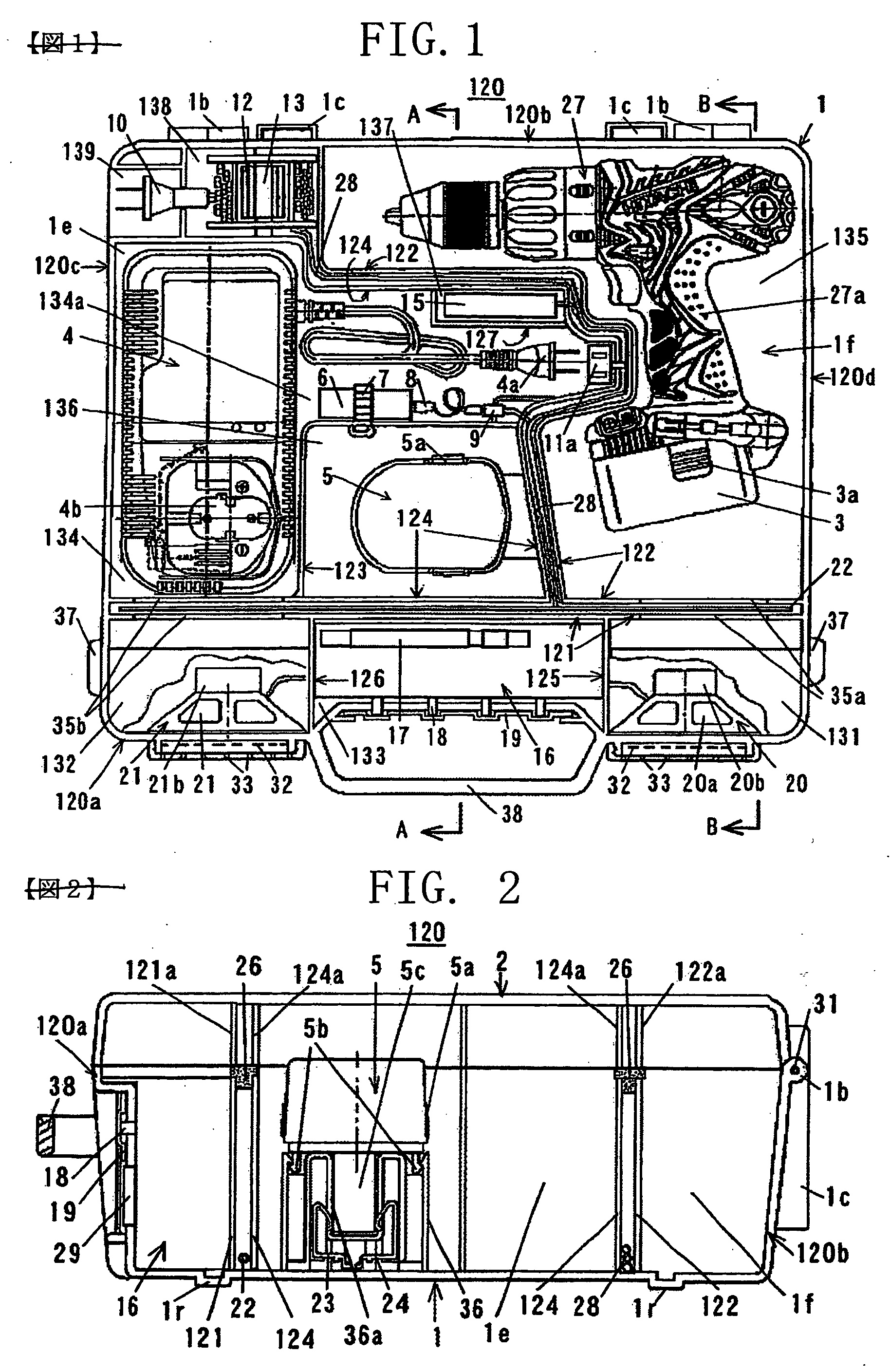
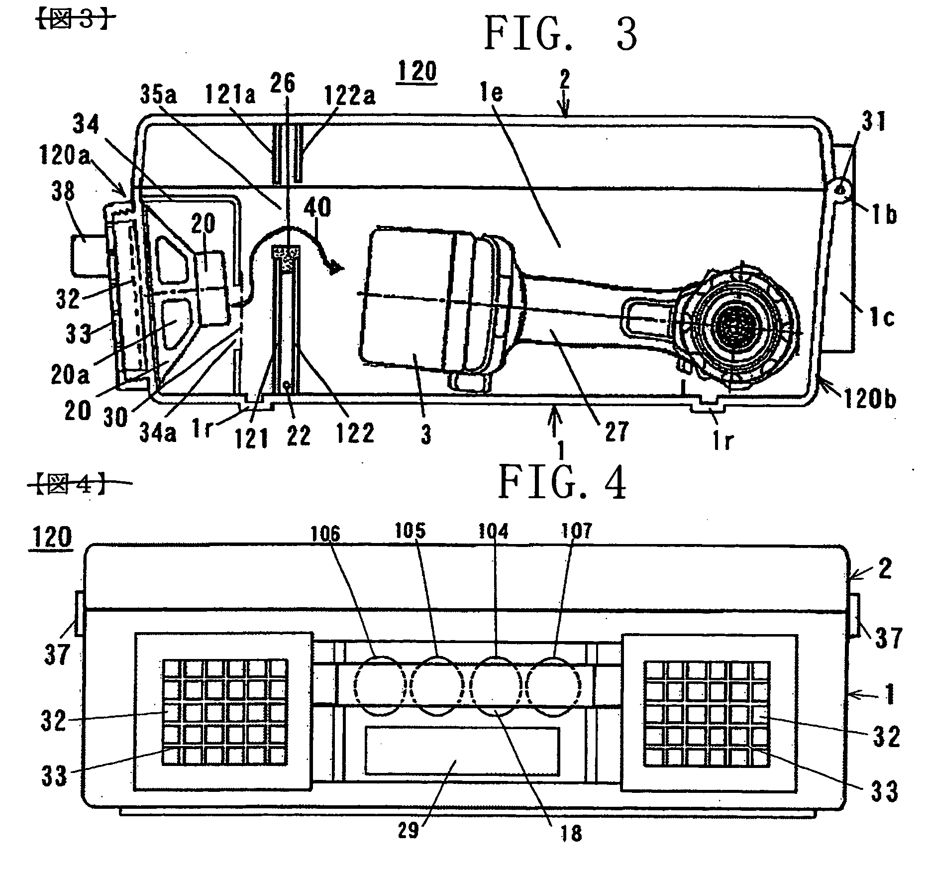
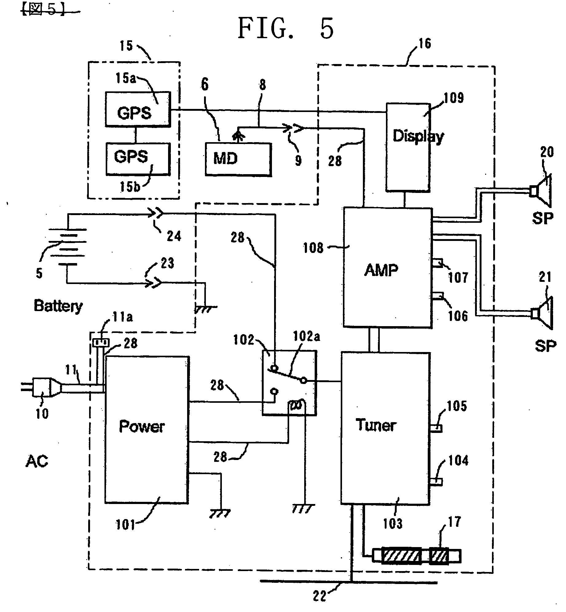
[0064] FIGS. 1 to 5 show a structure of an electric device mounting type tool storage case. In the electric device mounting type tool storage case, a driver drill body and the charger thereof are stored in a tool storage case for storing a cordless driver drill, and audio devices serving as another electric devices are mounted in the tool storage case. FIG. 1 is a plan view, FIG. 2 is a cross-sectional view taken along line A-A in FIG. 1, FIG. 3 is a cross-sectional view taken along line B-B in FIG. 1, FIG. 4 is a front view, and FIG. 5 is a circuit block diagram of the audio device.

[0065] Structure of Tool Storage Case and Speaker Enclosure

[0066] The tool storage case 120 according to the inven...


PUM


Abstract

An electric device mounting type tool storage case that is easily transported together with other electric devices such as audio devices in addition to an electric tool body and can stand against contamination such as dust in the work site. An audio device as an electric device can be stored in the tool storage case which is used as an enclosure of a pair of speakers. Storage portions disposed in the tool storage case are partitioned by partition walls into a pair of sound channel spaces. In addition, a power switching circuit of an AC-DC converter power supply circuit or a battery DC power supply is formed in the tool storage case, and power wiring lines or inner wiring lines are disposed along the partition walls. While a cover case closes a storage case, electric devices such as an audio device or a charger are operated.

Description

BACKGROUND OF THE INVENTION [0001] 1. Field of Invention [0002] The present invention relates to a tool storage case that is used to transports an electric tool body such as an impact driver used in a work site such as a construction site, or to stores the electric tool body therein when the electric tool body is unused. Specifically, the invention is related to an electric device mounting type tool storage case that is suitable for transporting other electric devices such as audio devices in addition to the electric tool body required in a work site. [0003] 2. Description of Related Art [0004] The audio device as disclosed in this specification has broad meaning including audio electric devices such as an audio amplifier, radio tuners (AM tuner, FM tuner, TV audio tuner), an MD player, a CD player, etc. [0005] In general, when an electric tool is transported to the work site, a storage case for the electric tool is used to conveniently transport the tool body, tip tools to be used ...

Claims


Application Information

Patent Timeline
IPC IPC(8): H02J7/00
CPCB25H3/006
Inventor YOSHIMIZU, CHIKAINAKAYAMA, EIJIHANAWA, HIROYUKITAKANO, NOBUHIRO
Owner HITACHI KOKI CO LTD
Why Eureka
Try Eureka