Machine component using ic tag and its method for controll quality and system for inspecting abnormality

a technology for machine components and tags, applied in the direction of electric programme control, programme control, total factory control, etc., can solve the problems of ic tag not having ic tag, ic tag being lost, trouble in machine components may not be ascertained, etc., to achieve easy attachment of components, increase manufacturing stages, and the effect of simple components

Inactive Publication Date: 2006-08-03
NTN CORP
View PDF6 Cites 52 Cited by
  • Summary
  • Abstract
  • Description
  • Claims
  • Application Information

AI Technical Summary

Benefits of technology

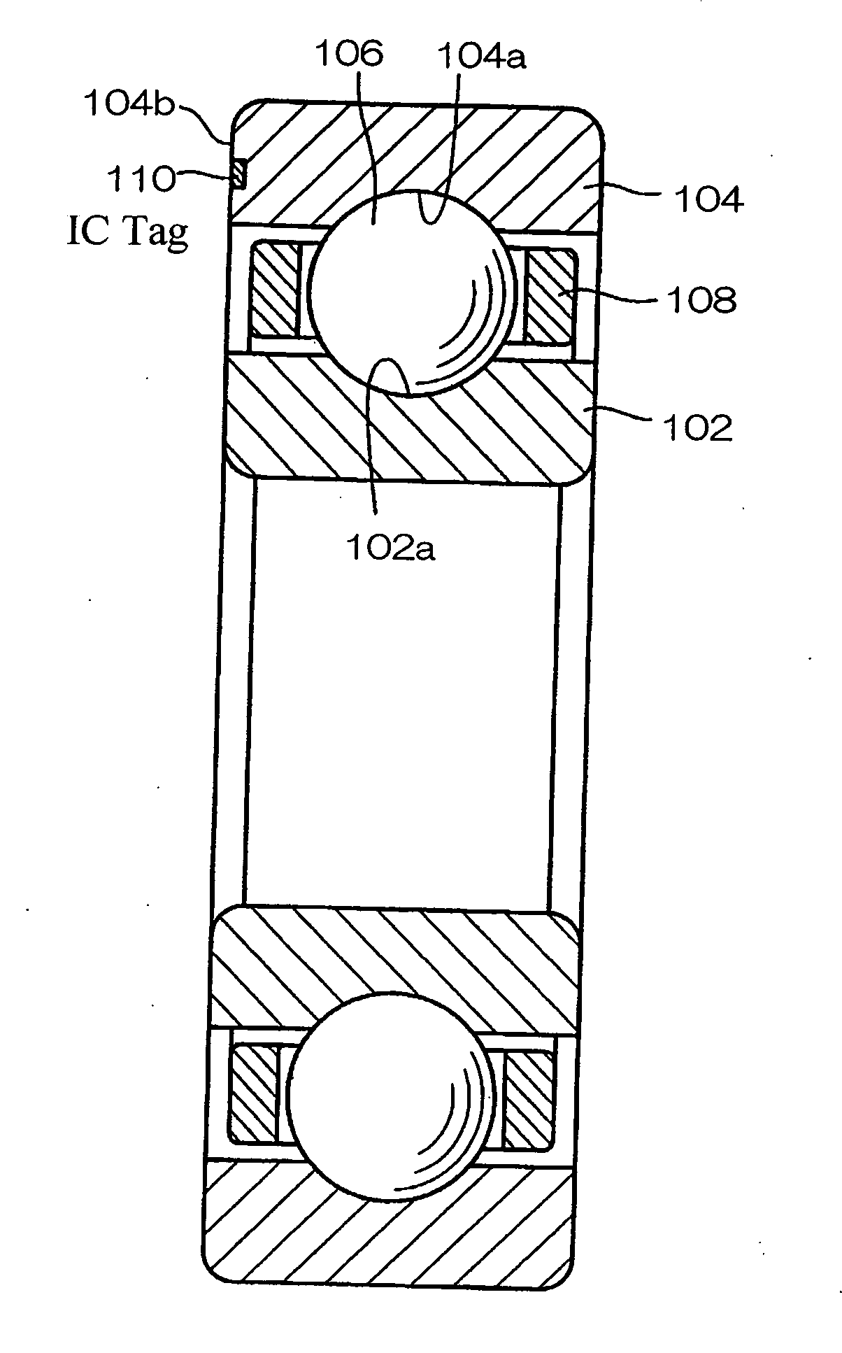
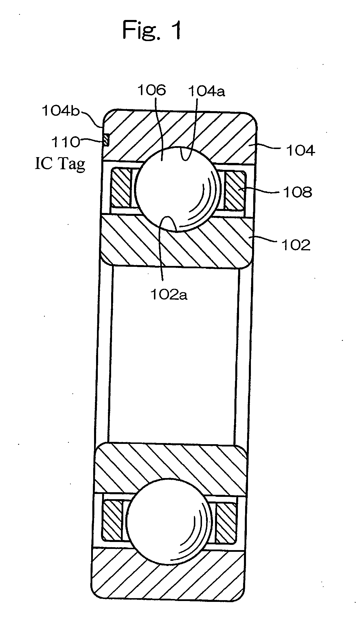
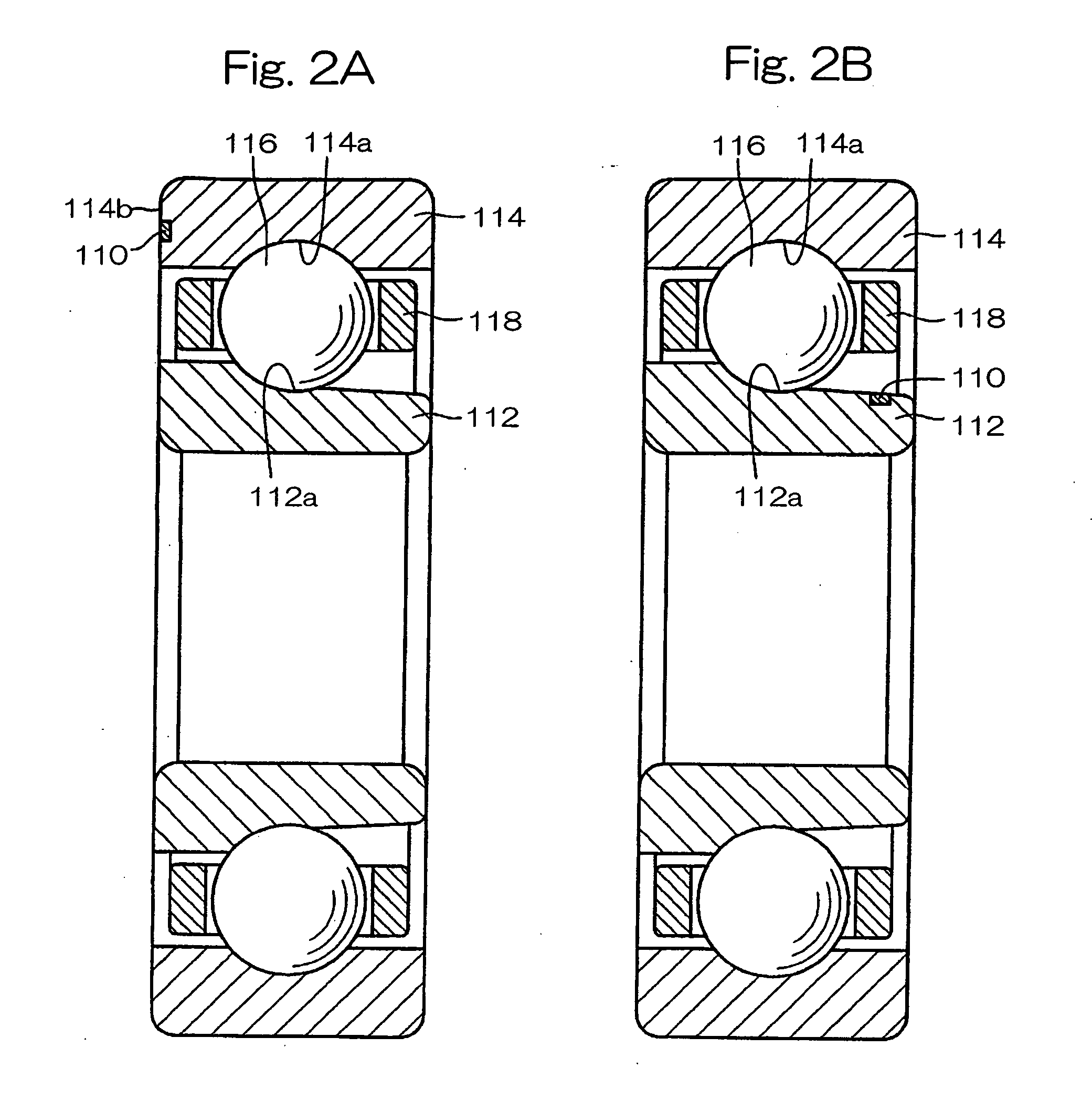
[0016] In view of the foregoing problems and inconveniences discussed hereinbefore, one object of the present invention is to provide a machine component having an IC tag attached thereto, which can be consistently controlled from manufacture to disposal thereof with no possibility of the IC tag being lost.
[0017] Another object of the present invention is to provide a quality control method for controlling machine components having a plurality of elements such as rolling elements, which method is effective to facilitate traceability and to enable identification of manufacturing information at each stage of the manufacturing process including forging, heat treatment and grinding to be accomplished even after shipment of those machine components or delivery thereof to the customer.
[0018] A further object of the present invention is to provide a quality control method for controlling machine components that are to be examined individually and that are formed by assembling a plurality of elements separately manufactured through a forging process, a heat treatment process and other processes, which method is effective to control the detailed histories of information on purchase of material for those elements to results of examination done after completion of the machine components, on a one-to-one basis with each of the machine components.

Problems solved by technology

However, any machine component carrying an IC tag has not yet been made available in the art, which can be consistently controlled from production to disposal with no possibility of the IC tag being lost.
However, the cause of trouble in the machine component may not be ascertained only with the information on the machine component.
By way of example, difference in processing condition at every stage of the manufacturing process often brings about difference in quality and such difference brought about by the difference in the processing condition cannot be often recognized from results of examination.
Considering that machine components such as rolling bearings, shaft couplings and ball screws are generally made up of a plurality of elements, even though the results of examination of the machine components are made available, it is virtually difficult to identify the presence or absence of any defect and / or trouble arising from the difference in quality of those elements.
In particular, in the case of the machine component including rolling elements of, for example, the rolling bearing, even slight difference in material and precision affects the performance of the resultant machine component and, therefore, the conventionally suggested quality control method using the IC tags is incapable of resolving those problems.
Also, as for the production control, the conventional control method in which data are recorded on a check note or sheet and / or inputted to a terminal device at every stage of the production process requires complicated and time-consuming procedures in accomplishing the recording and / or inputting and, therefore, it is quite difficult for a substantial amount of information to be recorded carefully and meticulously.
Specifically, in the case that machine components such as rolling bearings are made up of a plurality of elements and those elements are manufactured on a lot basis throughout the manufacturing process including purchase of material, forging stage, heat treatment stage and grinding stage, the control of those elements at every stage of the manufacturing process is complicated and it is time-consuming to record and input the history information on each of the elements by hand.
For this reason, it is difficult to provide the detailed information on history of the machine components, and the control of such information is costly.
In view of the foregoing, the use of the IC tag has been contemplated, but it has been found that the quality control system employed in association with articles of manufactures such as automobiles cannot be applied to the machine components of the kind discussed above.
However, considering that the machine components such as rolling bearings do not make use of any complete element usable as a standard object similar to the automobile frame and that during the manufacturing process those elements are manufactured through forging, heat treatment and the others, no IC tag can be affixed to each machine component itself from the beginning of the manufacturing process.
Also, since in the case of the machine components such as rolling bearings, inner races, outer races, rolling elements and other elements are controlled individually at each stage of the manufacturing process including, the purchase of material, a forging stage, a heat treatment stage and a grinding stage, it is difficult to determine how to use the IC tags for the quality control.
More specifically, it is difficult to determine which stage of the manufacturing process the IC tag is applied to and / or what portion of each machine component the IC tag should be attached to.
Thus, the efficient use of the IC tags is difficult.
It is often experienced that the rolling bearings are hardly controlled for lifetime despite of the needs for such control.
In contrast thereto, since each roller positioned generally intermediate of the length of the belt conveyor and supporting the endless belt makes use of hundreds of bearings, all of those bearings cannot be controlled individually in a manner similar to the major bearing portions of the drive unit and it is not realistic to monitor all of those bearings at all times in the terms of the cost.
When it comes to a railway vehicle in which a considerable number of bearings are employed for rotatably supporting wheels, once the railway vehicles start moving, they cannot be brought to a stop along the way in order to transport passengers and / or cargos to the destination.
Even with the intermediate rollers used to support the endless belt in the conventional thermal power plant, it is highly possible that the conveyor must be halted depending on the condition of damages once an abnormality occurs in the bearings.
However, the replacement of the bearings while the conveyor is being driven will not be accomplished in the event of an unforeseeable abnormality in the bearings.
Even where the early replacement is performed before the rated lifetime, an unforeseeable abnormality in the bearings may occur and no one can know in advancement when it occurs.
However, in the case of railway vehicles that are operated for a substantial period of time and over a long distance at high speeds, conditions of use of the wheel support bearings are indeed severe.
As such, the routine examination is not sufficient to prevent any abnormality in the bearings.
As a matter of course, the condition of the wheel support bearings while the railway vehicles are operated cannot be grasped when the railway vehicles are not operated.

Method used


Image

  • Machine component using ic tag and its method for controll quality and system for inspecting abnormality
  • Machine component using ic tag and its method for controll quality and system for inspecting abnormality
  • Machine component using ic tag and its method for controll quality and system for inspecting abnormality

Examples


fourth embodiment

[0141] In the practice of the fourth embodiment, the IC tag 9 is used to contain as many pieces of the manufacturing information as possible and the quality control is performed based on the recorded information. However, in the fifth preferred embodiment of the present invention, a post-shipment control database may be utilized and is generally identified by 10.

fifth embodiment

[0142] Specifically, the database 10 is used to store in association with the identifying information unique to the machine component 1 predetermined manufacturing information on purchase of material, the forging stage, the heat treatment stage, the grinding stage and the examination stage, so that the stored information in the database 10 can be extracted based on the identifying information. The quality control is carried out by the utilization of the database 10 and the IC tag 9 attached to the machine component 1. In this fifth embodiment, the following processing takes place during the steps R1 to 3.

(IC Tag Attaching Step R1)

[0143] This step R1 is substantially identical to that of the fourth embodiment.

(Manufacturing Information Recording Step R2)

[0144] At this step R2, by the time of shipment or delivery to a customer, identifying information of the machine component 1 such as serial number and lot number and manufacturing information on the machine component 1 are recor...

sixth embodiment

[0198] It is to be noted that although in the sixth embodiment the electric power source circuit 205 built in the IC tag 203 is utilized to drive the temperature sensor 204, an electric power source circuit 2052 separate from an electric power source circuit 205, for driving the IC tag 203 may be employed for driving the temperature sensor 204 as shown in FIG. 18. Even this electric power source circuit 2052 is electrically powered by an electric power supplied through the antenna 212. Also, the electric power source circuit 2052 may be provided with a rechargeable battery and a charging circuit 219 (not shown) as shown in FIG. 20.

[0199] Also, the bearing dedicated electronic component 206 may have a vibration sensor 217 as shown in FIG. 19 together with the temperature sensor 204. An output from the vibration sensor 217 is connected to, for example, a predetermined input terminal (not shown) of the IC tag 203. Where the vibration sensor 217 outputs an analog signal, it is inputted ...


PUM


Abstract

There is provided a machine component having an IC tag attached thereto, which can be controlled consistently from manufacture to disposal without the IC tag missed on the way. The machine component is embedded with the IC tag (110) made up of an IC chip having recorded thereon information unique to the relevant machine component and an antenna connected electrically with the IC chip.

Description

FIELD OF THE INVENTION [0001] The present invention relates to the consistent control of machine components such as rolling bearings, joints, hub bearings and clutches, which are embedded with IC tags utilizing the radio frequency identification (RFID) technology, from manufacture thereof to disposal. BACKGROUND ART [0002] The RFID technology is a generic term descriptive of a data identification method using radio frequencies or identifying media utilizing such data identification method and makes use of an RFID system including an IC tag serving as a data carrier, an IC tag reader / writer and an administrative personal computer. As shown in FIG. 4, the IC tag includes an IC chip, carrying data on merchandise or product information, and a miniature antenna, all embedded in a plastic card. The IC chip contains an ID memory and a communication control circuit. When the IC tag is attached to an object to be identified and information carried thereby is picked up by means of a reader / wr...

Claims


Application Information

Patent Timeline
Patent Type & Authority Applications(United States)
IPC IPC(8): G08B13/14F16C19/00F16C41/00G05B19/418
CPCF16C19/00F16C41/008G05B19/4183G06Q10/06F16C19/06F16C19/163F16C19/364F16C19/525F16C19/527F16C33/38F16C33/586F16C33/7843F16C2326/10F16C2326/58Y02P90/02G05B19/418G06K17/00
Inventor NAKAMURA, SHOHEIHIOKI, SHOUICHIITO, HIROYOSHIMAYUMI, TOORUSASABE, MITSUO
Owner NTN CORP
Why Eureka
Try Eureka