
Ferrite magnet powder, sintered magnet, bond magnet, and magnetic recording medium

Inactive Publication Date: 2006-08-03
TDK CORPARATION
View PDF3 Cites 5 Cited by
  • Summary
  • Abstract
  • Description
  • Claims
  • Application Information

AI Technical Summary

Benefits of technology

[0008] The present inventors have conducted various studies direct towards achieving the aforementioned object. The inventors have attempted to obtain a hard ferrite material, which exhibits a saturation magnetization 4πIs and a residual magnetic flux density Br that are higher than those of conventional ferrite materials. As a result, the inventors have found that the partial substitution of the Fe2+ site of a W-type ferrite with a specific element such as Zn within a certain range is extremely effective for obtaining a high saturation magnetization 4πIs and a high residual magnetic flux density Br without impairing squareness. That is to say, the present invention relates to a ferrite magnet powder represented by the composition formula AFe2+a(1-x)MaxFe3+bO27, wherein A represents at least one element selected from the group consisting of Sr, Ba, and Pb; and M represents at least one element selected from the group consisting of Zn, Co, Mn, and Ni, characterized in that 0.05≦x≦0.80, 1.5≦a≦2.2, and 12≦b≦17. In the ferrite magnet powder of the present invention, a crystal phase identified by X-ray diffraction comprises a W phase as a main phase. Herein, when the molar ratio of a W phase calculated from X-ray diffraction intensity is 50% or more in the present invention, it is determined that the W phase is a main phase. The ferrite magnet powder of the present invention enables the comprising of a W phase at a ratio of 90% or more, or also enables the comprising of a W phase as a single phase. It is to be noted that the comprising of a W phase as a single phase means that the molar ratio of the W phase is found to be almost 100%.
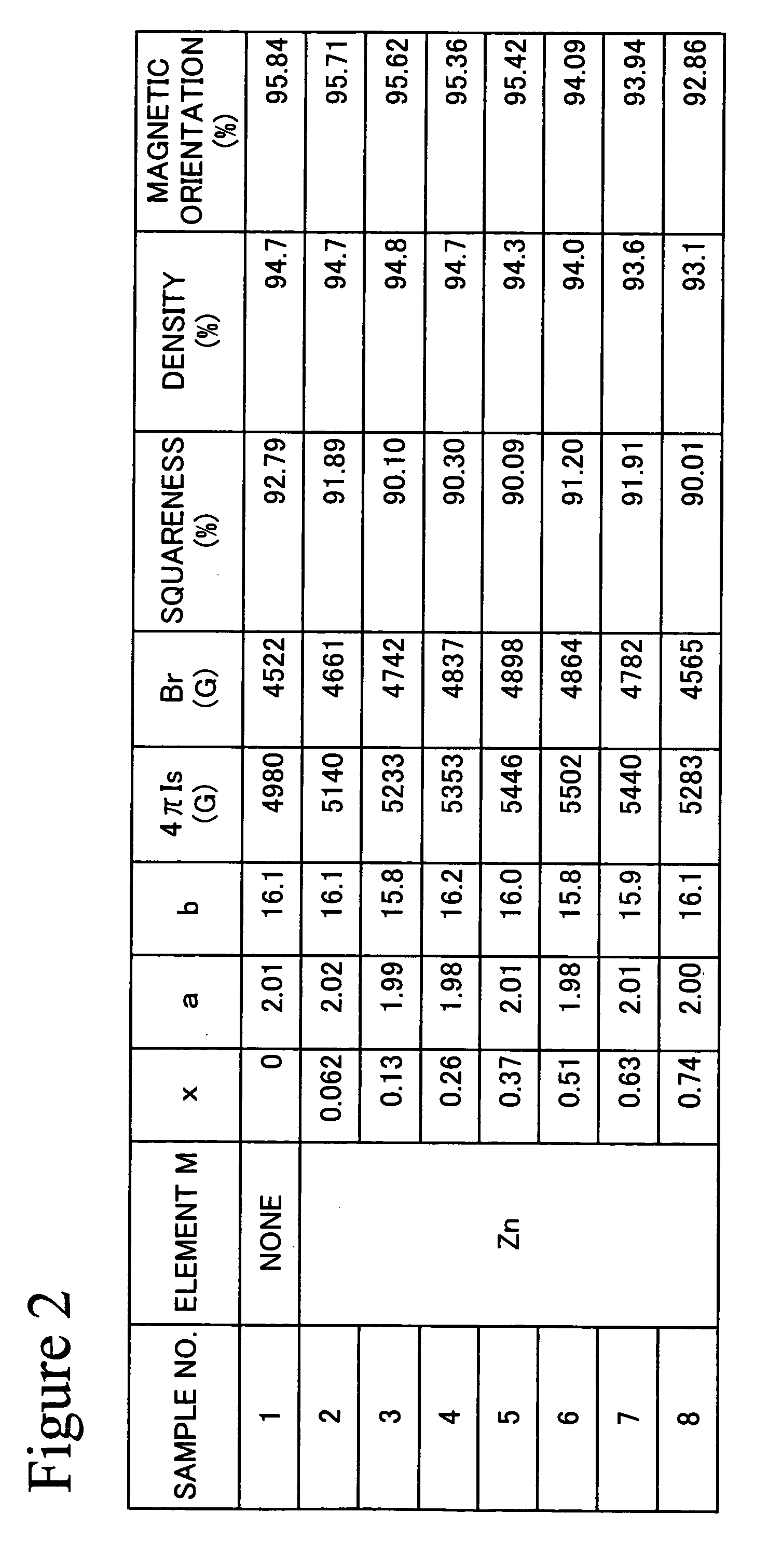
[0011] The ferrite magnet powder of the present invention has excellent properties such as a saturation magnetization of 5.0 kG or more, and preferably 5.1 kG or more.
[0013] Still further, the present invention provides a sintered magnet comprising, at a molar ratio of 50% or more, a W-type hexagonal ferrite comprising an element A, wherein A represents at least one element selected from the group consisting of Sr, Ba, and Pb, Fe2+, and Fe3+, characterized in that the Fe2+ site of the above described W-type hexagonal ferrite is partially substituted with an element M, wherein M represents at least one element selected from the group consisting of Zn, Co, Mn, and Ni. These sintered magnets exhibit excellent properties such as a saturation magnetization of 5.0 kG or more, and preferably 5.1 kG or more.

Problems solved by technology

Thus, it is difficult to make a dramatic improvement of magnetic properties under the present circumstances.

Method used


Image

  • Ferrite magnet powder, sintered magnet, bond magnet, and magnetic recording medium
  • Ferrite magnet powder, sintered magnet, bond magnet, and magnetic recording medium
  • Ferrite magnet powder, sintered magnet, bond magnet, and magnetic recording medium

Examples


example 1

[0062] An experimental example, in which Zn was selected as element M, will be given below as Example 1.

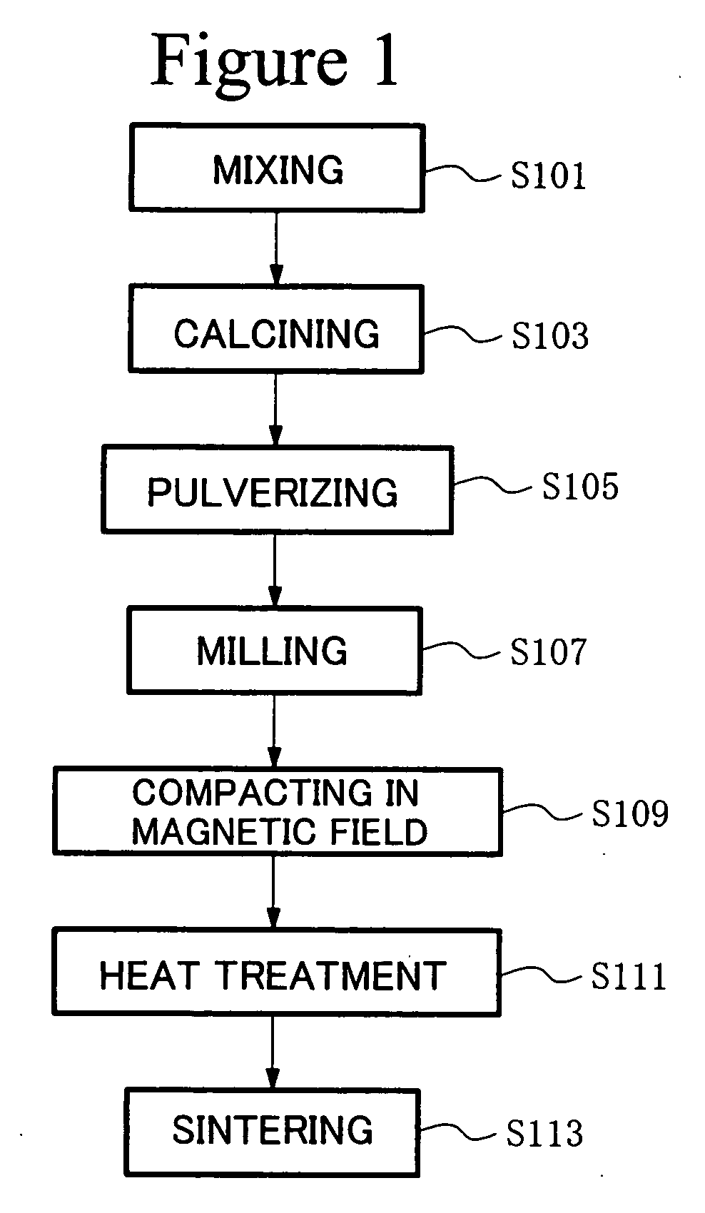
[0063] The sintered magnet of the present invention was produced in accordance with the following procedures.

[0064] Fe2O3 powders (primary particle size: 0.3 μm), SrCO3 powders (primary particle size: 2 μm), and ZnO powders (primary particle size: 0.3 μm) were prepared as raw material powders. These raw material powders were weighed, resulting in given values. That is, each of the raw material powders was weighed, such that the composition of the finally obtained sintered magnet could be set within the range as shown in formula (1). After completion of the weighing, these powders were mixed and crushed using a wet attritor for 2 hours. Subsequently, the crushed powders were dried, and the particle size thereof was then regulated. Thereafter, the powders were calcined in a nitrogen atmosphere at 1300° C. for 1 hour, so as to obtain a powdery calcined body. 220 g of the calcined b...

example 2

[0080] Three types of sintered bodies (sample Nos. 9, 10, and 11) having the composition represented by the formula AFe2+a(1-x)MaxFe3+bO27, wherein the values of a, b, and x are shown in FIG. 9, were produced under the same conditions as those applied in Example 1 with the following exceptions. Thereafter, the magnetic properties of the sintered bodies were evaluated under the same conditions as those applied in Example 1. The results are shown in FIG. 9.

9>

[0081] The following types of additives and additive amounts were determined with respect to 210 g of the calcined body. [0082] SiO2 powders (primary particle size: 0.01 μm) 0.6% by weight [0083] CaCO3 powders (primary particle size: 1 μm) 0.7% by weight [0084] Sorbitol (primary particle size: 10 μm) 1.2% by weight [0085] Carbon powders (primary particle size: 0.05 μm) 0.25% by weight [0086] SrCO3 powders (primary particle size: 2 [m) 1.5% by weight

10>

[0087] The following types of additives and additive amounts were determined w...

example 3

[0104] An experimental example, in which Co, Mn, and Ni were selected as element M, will be given below as Example 3.

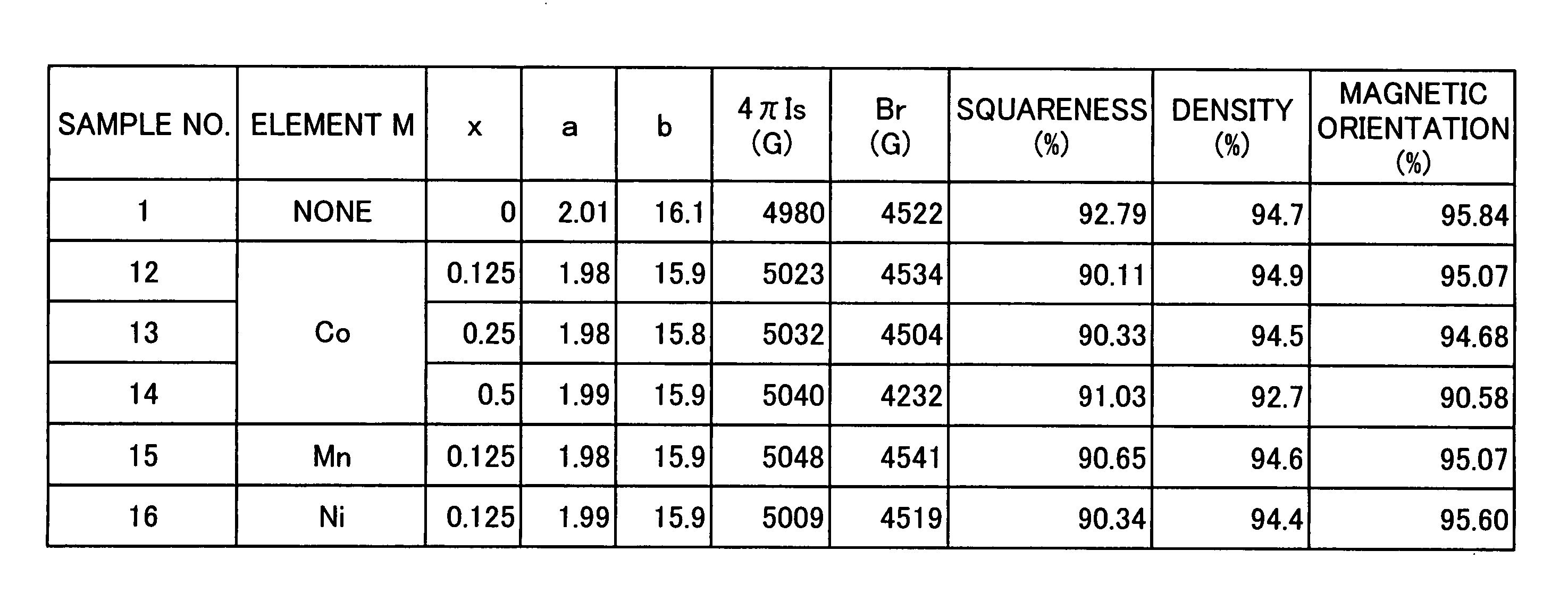
[0105] Five types of sintered bodies having the composition represented by the formula SrFe2+a(1-x)MaxFe3+bO27, wherein the values of a, b, and x are shown in FIG. 10, were produced in accordance with the same procedures as those applied in Example 1. Thereafter, the magnetic properties of the sintered bodies were evaluated under the same conditions as those applied in Example 1. The results are shown in FIG. 10. FIG. 10 also shows density and magnetic orientation.

[0106] As shown in FIG. 10, even when the Fe2+ site was partially substituted with any one of Co, Mn, and Ni, the sintered body had a 4πIs that was higher than sample No. 1 that had not been substituted, while exhibiting a good squareness of 90% or more.

[0107] In addition, the phase states of sample Nos. 12 to 16 were identified under the same conditions as those applied in Example 1. As a result, it was ...


PUM

PropertyMeasurementUnit
Fractionaaaaaaaaaa
Fractionaaaaaaaaaa
Magnetizationaaaaaaaaaa

Abstract

A ferrite magnet powder is represented by the composition formula AFe2+a(1-x)MaxFe3+bO27, wherein A represents at least one element selected from the group consisting of Sr, Ba, and Pb; and M represents at least one element selected from the group consisting of Zn, Co, Mn, and Ni, and wherein 0.05≦x≦0.80, 1.5≦a≦2.2, and 12≦b≦17. A high saturation magnetization 4πIs can be achieved by the partial substitution of the Fe2+ site of a W-type ferrite with an element M such as Zn within a certain range.

Description

TECHNICAL FIELD [0001] The present invention relates to a technique of improving the magnetic properties of hard ferrite materials, in particular, a W-type hexagonal ferrite magnet. BACKGROUND ART [0002] A magneto plumbite-type hexagonal ferrite including SrO.6Fe2O3 as a representative example, that is, an M-type ferrite, has previously remained a mainstream of ferrite sintered magnets. With regard to such an M-type ferrite magnet, efforts have been made to achieve a higher performance thereof, centering on the purposes that the grain size of a ferrite crystal is brought close to that of a single domain, that ferrite grains are aligned in a magnetic anisotropic direction, and that a high-density sintered body is achieved. As a result of such efforts, the properties of an M-type ferrite magnet are close to its upper limit. Thus, it is difficult to make a dramatic improvement of magnetic properties under the present circumstances. [0003] W-type ferrite magnet has been known as a ferri...

Claims


Application Information

Patent Timeline
IPC IPC(8): G11B5/65H01F1/00C04B35/26G11B5/706H01F1/11H01F1/113
CPCC01G49/0036Y10T428/32C01G49/0072C01G49/009C01P2002/72C01P2004/03C01P2006/42C04B35/2608C04B35/2633C04B35/6265C04B2235/3208C04B2235/3213C04B2235/3215C04B2235/3262C04B2235/3275C04B2235/3279C04B2235/3284C04B2235/3418C04B2235/5445C04B2235/605C04B2235/652C04B2235/77G11B5/70678H01F1/11H01F1/113C01G49/0063
Inventor MINACHI, YOSHIHIKOITO, NOBORU
Owner TDK CORPARATION
Learn More