Method, apparatus and system for controlling a gas-fired heater

a technology for controlling apparatus and gas-fired heaters, applied in the field of control systems, can solve the problems of affecting the safety of gas-fired heaters, and affecting the operation of gas-fired heaters, so as to reduce the introduction of natural gas, reduce the need for unsafe pilot lighting procedures, and reduce the effect of natural gas venting

Inactive Publication Date: 2006-08-03
SURE FIRE PILOTLESS BURNER SYST
View PDF14 Cites 29 Cited by
  • Summary
  • Abstract
  • Description
  • Claims
  • Application Information

AI Technical Summary

Benefits of technology

[0007] The present invention provides a system, method and apparatus for controlling a gas-fired heater that is dependable, durable, efficient, inexpensive, reliable and removes the need for unsafe pilot lighting procedures, reduces the introduction of natural gas vented into the atmosphere caused by pilot or main boiler tube flame outs, reduces the amount of human operator attendance time, as well as emergency call outs due to flame outs, and eliminates freeze-up due to pilot or main boiler tube flame outs. Moreover, the present invention provides a cost reduction to wellhead operations which utilize any boiler tube application. Savings can conservatively approach a two year payout for system users. Savings are experienced because there is no longer a pilot, which may be lit for six months or more of the year. There is also savings by a decrease in lost production, which is experienced when wellhead boiler equipment is inoperative.

Problems solved by technology

When temperatures fall below freezing, or to a temperature that would disrupt normal operations, the wellhead equipment that is installed on a producing oil or gas well to control and regulate the flow of oil or gas can freeze-up and cease to function.
These freeze-ups are quite expensive because valuable production is lost and skilled workers have to be dispatched to the well site to remedy the freeze-up and restore the production of oil or gas from the well.
Moreover, traveling to these well sites, which are typically in remote, hard to reach areas, is difficult and often hazardous.
Likewise, working in below freezing conditions is also difficult and hazardous.
Other more expensive, complicated, and maintenance intensive solutions have been proposed, such as insulated jackets (e.g., U.S. Pat. No. 5,049,724 issued to Anderson on Sep. 17, 1991), infrared heaters (e.g., U.S. Pat. No. 6,776,227 issued to Beida et al on Aug. 17, 2004), and engine coolant (e.g., U.S. Pat. No. 6,032,732 issued to Yewell on Mar. 7, 2000).
Often these more sophisticated heating systems are just not feasible for the remote areas that are most likely to have freeze-ups because they typically require the installation and maintenance of additional equipment and the storage of refined fuels to run the heaters
Gas-fired heaters, on the other hand, are often fueled by natural gas diverted from the well, which reduces the amount of equipment that must be installed and maintained.
But these gas-fired heaters typically rely on pilot lights to start the heaters.
But these pilots often go out, especially in bad weather.
When the pilot light goes out and the heater is activated, the fuel gas is vented (wasted), the wellhead freezes, production volumes are decreased and the operator's time is consumed.
Moreover, the vented fuel gas poses numerous safety and environmental problems.
As a result, these existing gas-fired heaters can be costly due to lost fuel gas volumes, lost production volumes, lost productivity of employees, the safety considerations of manually lighting heaters, and the environmental considerations of vented gas.
Although pilotless heaters have been used in commercial and residential applications for some time, these systems will not survive or function properly in the harsh environmental conditions at a well site (e.g., cold, wind, moisture, corrosive elements, unclean fuel, etc.).

Method used


Image

  • Method, apparatus and system for controlling a gas-fired heater
  • Method, apparatus and system for controlling a gas-fired heater
  • Method, apparatus and system for controlling a gas-fired heater

Examples


Embodiment Construction

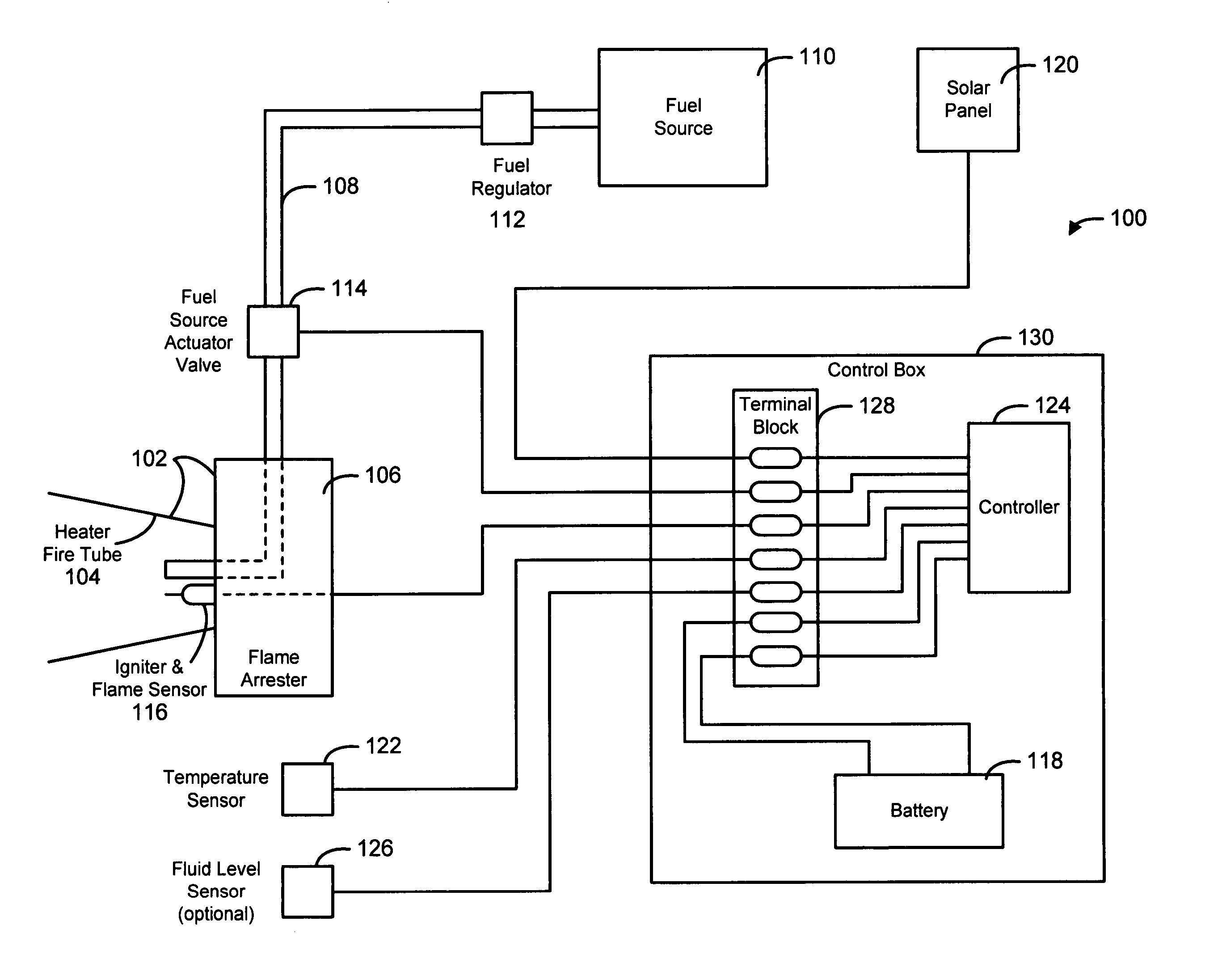
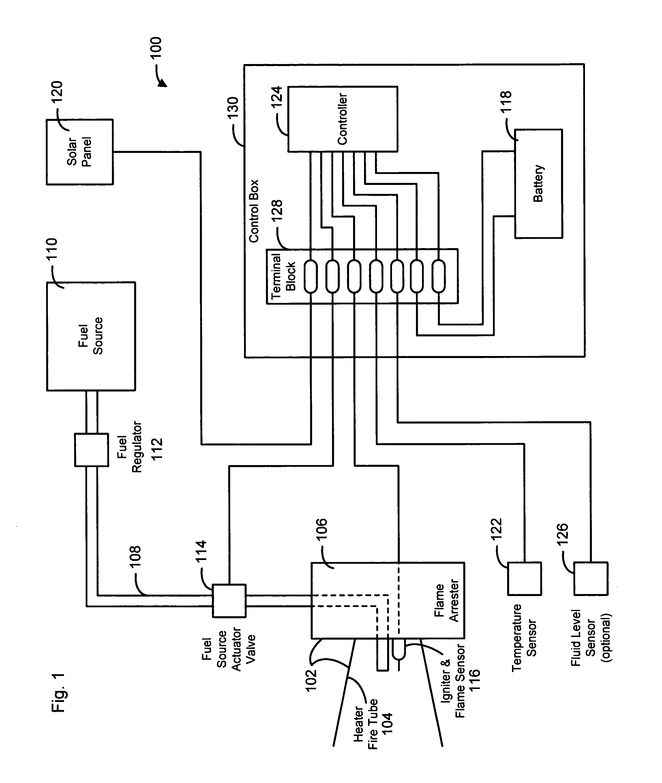
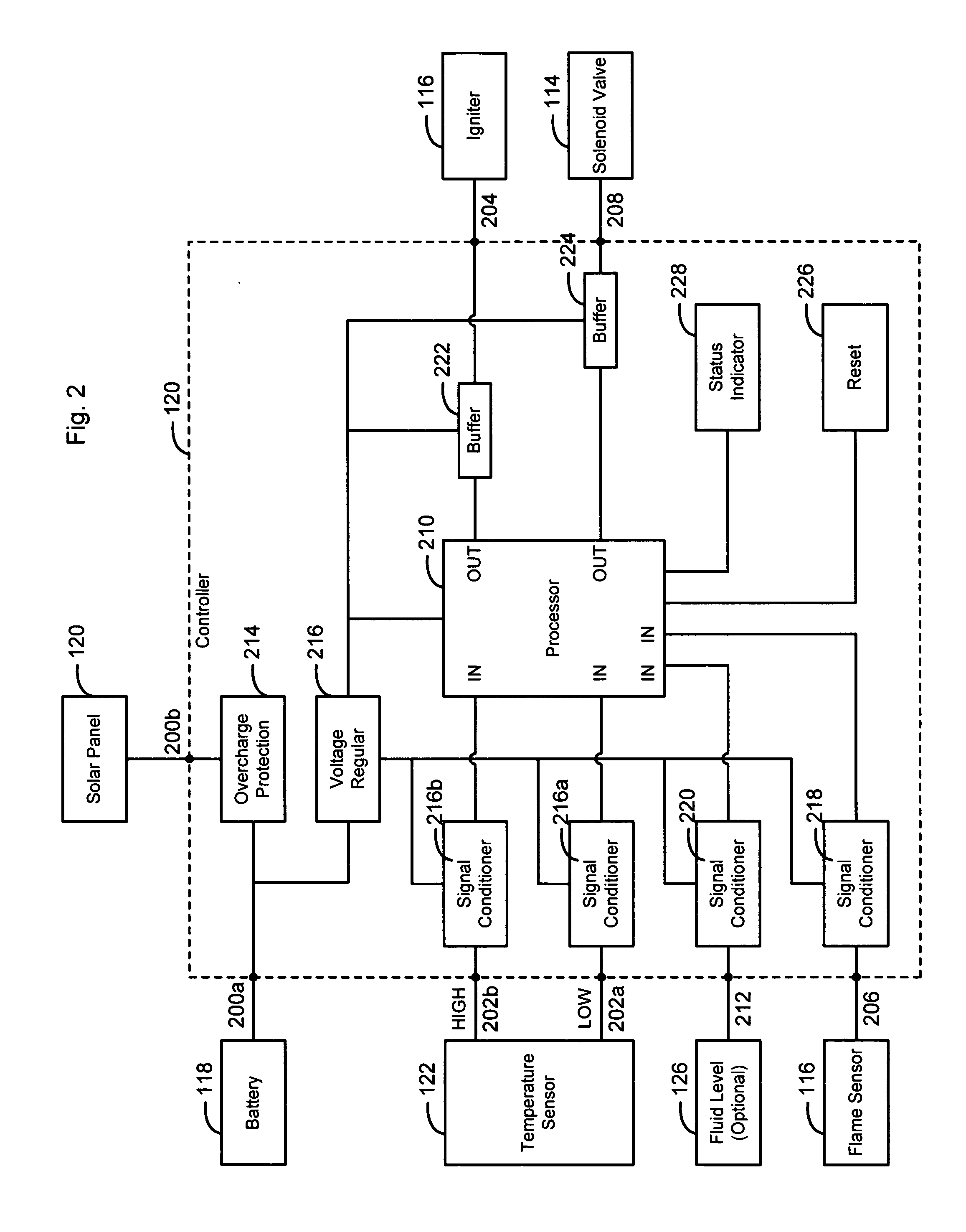
[0022] While the making and using of various embodiments of the present invention are discussed in detail below with respect to a pilotless igniter system, it should be appreciated that the present invention provides many applicable inventive concepts that can be embodied in a wide variety of specific contexts, including but not limited to, any boiler or gas-fired heater tube application, such as wellheads, natural gas and natural gas liquids processing plants, natural gas and natural gas liquids purification plants, and petrochemical complexes. As a result, the terminology used and specific embodiments discussed herein are merely illustrative of specific ways to make and use the invention and do not delimit the scope of the invention.

[0023] The present invention provides a system, method and apparatus for controlling a gas-fired heater that is dependable, durable, efficient, inexpensive, reliable and removes the need for unsafe pilot lighting procedures, reduces the introduction o...


PUM


Abstract

The present invention provides a system, method and apparatus for controlling a gas-fired heater connected to a fuel source via a fuel source valve that includes one or more power sources, a temperature sensor, a pilotless igniter disposed within the gas-fired heater, a flame sensor disposed within the gas-fired heater and a controller electrically connected to the one or more power sources, the temperature sensor, the pilotless igniter, the flame sensor and the fuel source valve. The controller turns the pilotless igniter on for a first time period and opens the fuel source valve whenever the temperature sensor indicates that a temperature is less than or equal to a low temperature setting. The controller also closes the fuel source valve whenever the temperature sensor indicates that the temperature is greater than or equal to a high temperature setting or the flame sensor indicates that a flame has gone out.

Description

TECHNICAL FIELD OF THE INVENTION [0001] The present invention relates, in general, to the field of control systems, and in particular, to a method, apparatus and system for controlling a gas-fired heater. BACKGROUND OF THE INVENTION [0002] Without limiting the scope of the invention, the background of the invention is described in connection with wellhead equipment for oil and gas wells in regions that experience extremely cold winters, such as at high altitude, or in Alaska, Canada, Siberia, etc. When temperatures fall below freezing, or to a temperature that would disrupt normal operations, the wellhead equipment that is installed on a producing oil or gas well to control and regulate the flow of oil or gas can freeze-up and cease to function. These freeze-ups are quite expensive because valuable production is lost and skilled workers have to be dispatched to the well site to remedy the freeze-up and restore the production of oil or gas from the well. Moreover, traveling to these ...

Claims


Application Information

Patent Timeline
Patent Type & Authority Applications(United States)
IPC IPC(8): F23N5/00
CPCF23N5/143F23N2023/38F23N2025/14F23N2027/42F23N2031/02F23N2031/24F23N2223/38F23N2225/14F23N2227/42F23N2231/02F23N2231/24
Inventor COOK, RONNIE
Owner SURE FIRE PILOTLESS BURNER SYST
Why Eureka
Try Eureka