Gynecological brachytherapy applicator and system

a brachytherapy and applicator technology, applied in the field of gynecological brachytherapy applicator and system, can solve the problems of not being able to provide a good fit, less than ideal treatment, and often uncomfortable or painful applications, and achieve accurate delivery dose profile, prevent or limit balloon expansion, and reduce the effect of balloon expansion

Inactive Publication Date: 2006-08-03
XOFT INC
View PDF12 Cites 109 Cited by
  • Summary
  • Abstract
  • Description
  • Claims
  • Application Information

AI Technical Summary

Benefits of technology

[0005] In one preferred implementation of the invention, a brachytherapy applicator comprises an inflatable balloon, with a shaft extending into the interior of the balloon, the shaft having a conduit for inflating the balloon by admitting fluid to the balloon's interior. A source of ionizing radiation for delivery of radiation is affixed to or retained at the distal end of a flexible catheter or a rigid wand, depending on the application at hand. The source catheter or wand is contained in or received in the applicator shaft and is guided into the space within the balloon. A fluid tight seal, such as by a bonded joint, is provided at the proximal end of the balloon to seal the balloon against the exterior of the shaft in this embodiment. At the interior of the proximal end of the shaft in this preferred embodiment, an O-ring seal seals the shaft to the exterior of the flexible catheter or rigid wand comprising the radiation source, permitting rotation as well as axial movement between the radiation source structure and the shaft without substantial fluid leakage.
[0006] The radiation source may be omni directional or direction specific to suit the application. In one embodiment a radio opaque source guide including a radiation window is provided between the shaft and the source catheter or wand to control the directionality of emitted radiation. The radiation source and source guide can be rotatable within the shaft without substantial loss of fluid from the interior of the balloon. A preferred form of the shaft is configured to allow pullback of the radiation source.
[0010] Another preferred feature of the invention is a means for adjusting the size of the inflated portion of the balloon. This can be accomplished using a slidable tubular sheath over the shaft that slides axially relative to the shaft, and when moved forward (distally), covers a desired portion of the balloon from the proximal end of the balloon so as to prevent or limit expansion of the balloon in the sheath-covered portion. The expanded length of the balloon is thus limited as desired. This adjustment accommodates different anatomies of different patients, as well as adjusts for different regions within the anatomy.
[0011] As noted above, the source of ionizing radiation in a particular preferred embodiment is an electronic switchable x-ray source, which is not only switchable on / off but is adjustable as to voltage and current, and thus as to x-ray penetration depth and cumulative dose delivered. This affords attaining a much more accurate delivered dose profile than can be obtained using prior art methods since the control of radiation allows accommodation of differences in distance from source to tissue and differences in dose delivered to different tissue regions. It also provides a more flexible and anatomy-conforming applicator.
[0013] It is thus among the objects of the invention to greatly improve efficiency, reliability, versatility, patient comfort and dose accuracy in brachytherapy radiation within the vaginal cavity and adjacent anatomy. These and other objects, advantages and features of the invention will be apparent from the following description of preferred embodiments, considered along with the accompanying drawings.

Problems solved by technology

Even though the applicator cylinders are sized to the vaginal cavity or adjacent anatomy, these types of applicators have often been uncomfortable or painful on insertion and once inserted have failed to provide a good fit.
The conventional applicator can cause discomfort, inconvenience and less than ideal treatment in many cases.
Such devices also lack flexibility in dose delivery profile.

Method used


Image

  • Gynecological brachytherapy applicator and system
  • Gynecological brachytherapy applicator and system
  • Gynecological brachytherapy applicator and system

Examples


Embodiment Construction

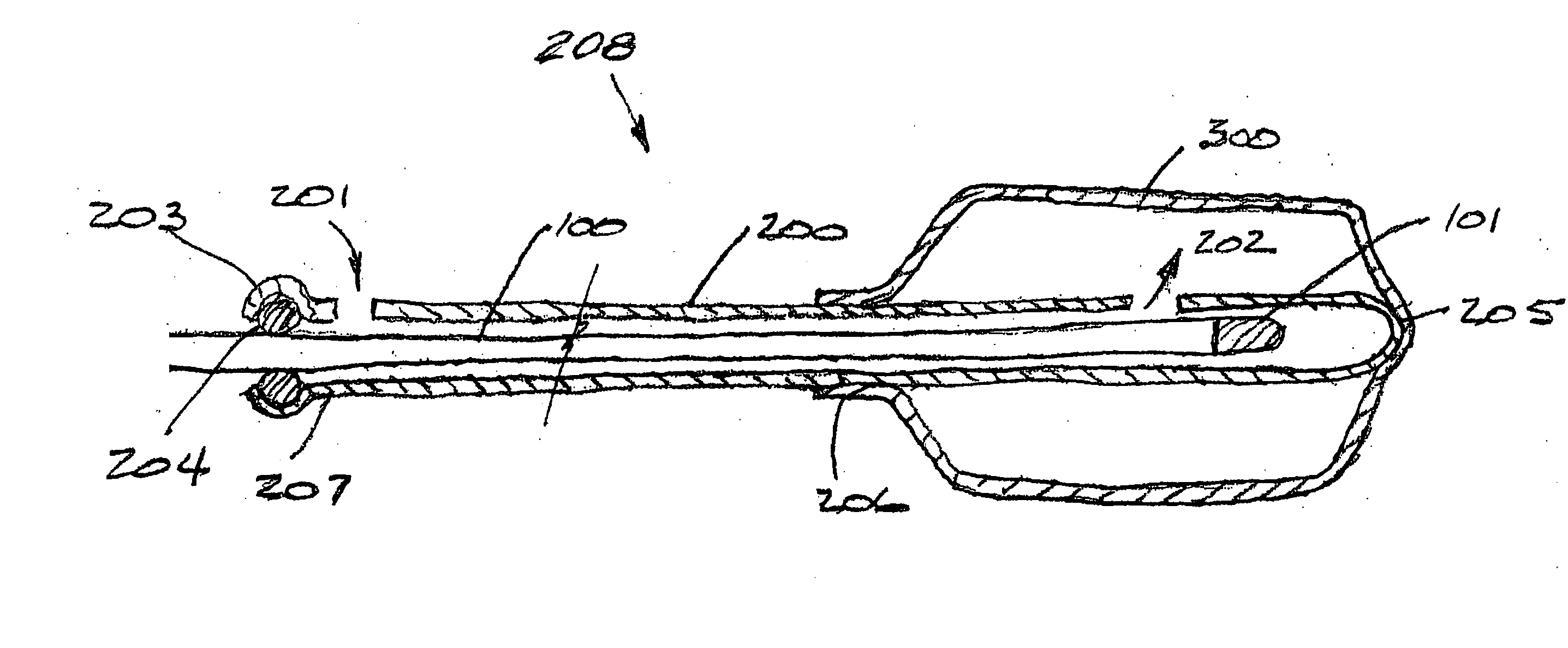
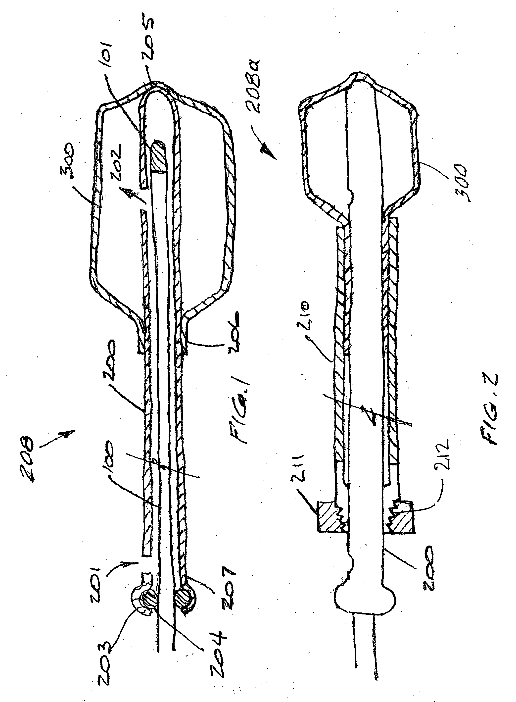
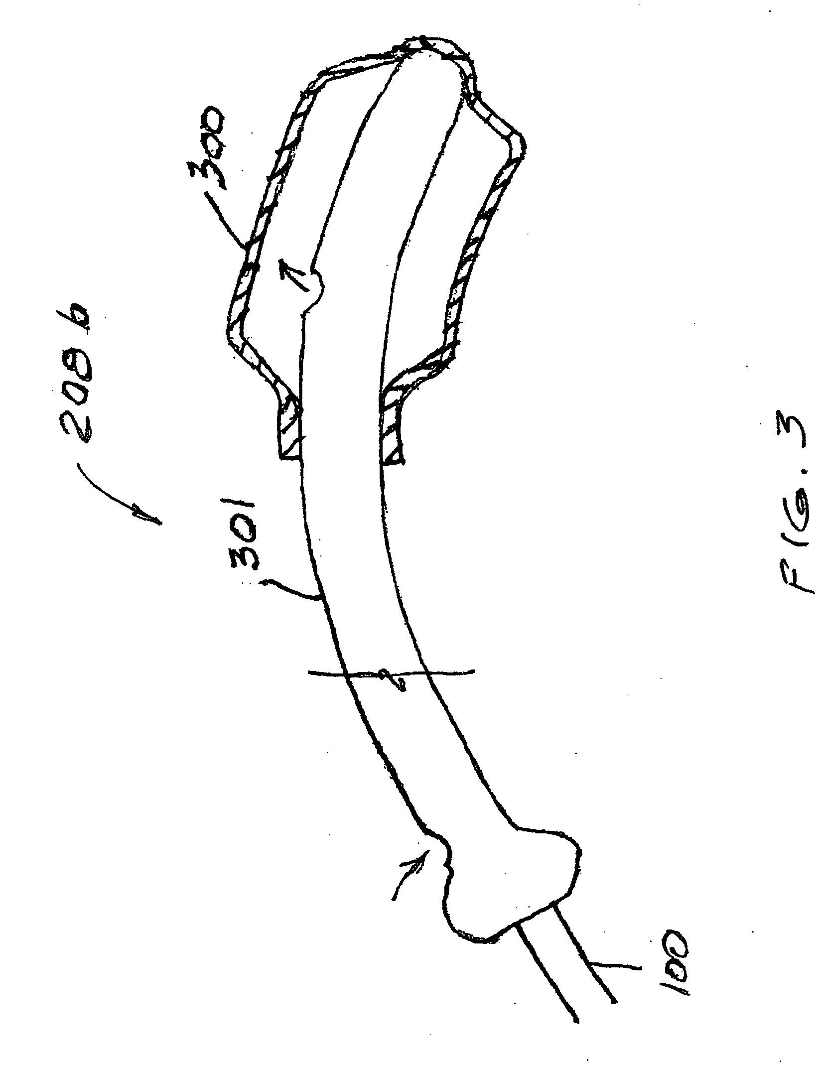
[0027]FIG. 1 depicts a basic embodiment of the invention. A radiation source catheter or wand 100 has a radiation source 101 at its distal end. The catheter or wand 100 is shown assembled within a shaft 200. The shaft 200 comprises a tubular body with a balloon 300 at its distal end 205. The distal end of the shaft 200 is bonded to the balloon at its distal extremity, and bonded to the balloon proximal extremity at 206.

[0028] At the proximal end 207 of the shaft 200 is a conventional applicator hub (not shown) as is common in radiation applicators, including a port 201 for balloon inflation fluid in communication with a fluid outlet 202 within the balloon, and a seal receptacle 203 for an O-ring 204. The O-ring 204 maintains a movable seal between the shaft 200 and the catheter 100 in this embodiment, allowing both rotation and translation of the catheter within the shaft without loss of balloon inflation pressure.

[0029]FIG. 2 shows an optional tubular sheath 210 placed over and c...


PUM


Abstract

A vaginal brachytherapy applicator is versatile to different anatomies and more comfortable to the patient than prior applicators. An inflatable balloon on a shaft may be inelastic or elastic. In one embodiment the shaft is rotatable relative to the balloon for enabling a ring or band of dose delivery, for versatility in radiation placement. Alternatively, the source can be rotated and pulled back within a stationary shaft. An adjustment is provided for reducing the length of balloon that inflates, to accommodate different anatomies and positions. Although isotope radiation sources can be used in the applicator, an electronic source is preferred, and the system and method include procedures for using the applicator with an electronic source.

Description

[0001] This application is a continuation-in-part of application Ser. No. 10 / 464,140, filed Jun. 18, 2003.BACKGROUND OF THE INVENTION [0002] This invention concerns radiation therapy, especially for treating tissue which may have malignancies, and in particular the invention relates to an applicator for delivering radiation to a vaginal cavity and / or to adjacent tissue post full / partial hysterectomy for surgical treatment of cancer. Treatment of endometrial cancer is encompassed by the invention. [0003] Vaginal or endometrial cancer, or malignancies in adjacent tissues, have been treated by applicator cylinders designed to receive radioactive isotopes. Applicators of this general type are shown, for example, in U.S. Pat. Nos. 5,913,813 and 6,413,204. Even though the applicator cylinders are sized to the vaginal cavity or adjacent anatomy, these types of applicators have often been uncomfortable or painful on insertion and once inserted have failed to provide a good fit. Ideally, the...

Claims


Application Information

Patent Timeline
Patent Type & Authority Applications(United States)
IPC IPC(8): A61N5/00A61N5/10
CPCA61N5/1016A61N5/1048A61N2005/1005
Inventor LIM, ALEXLOVOI, PAUL A.HAUSEN, HEIKESTEWART, DAREN L.
Owner XOFT INC
Why Eureka
Try Eureka