Methods and systems for reducing RF-induced heating in magnetic resonance imaging

a technology of magnetic resonance imaging and rf, applied in the field of interventional imaging, can solve the problems of large current and/or voltage, potentially dangerous heating effects, and serious fabrication issues of techniques, and achieve the effect of avoiding current and/or voltage built-up on the wir

Inactive Publication Date: 2006-08-03
GENERAL ELECTRIC CO
View PDF5 Cites 14 Cited by
  • Summary
  • Abstract
  • Description
  • Claims
  • Application Information

AI Technical Summary

Benefits of technology

[0005] Briefly, in accordance with one aspect of the present technique, a conducting wire assembly is provided for use with a magnetic resonance imaging (MRI) system. The conducting wire assembly includes at least one impedance component coupled externally to a conducting wire. The impedance component is configured to dynamically vary an impedance of the conducting wire to disrupt resonant conditions of the conducting wire and to avoid current and / or voltage built-up on the wire.
[0006] In accordance with another aspect, a method for reducing RF-induced heating in magnetic resonance imaging (MRI) is provided. The method includes externally coupling an impedance component to a conducting wire and dynamically varying an impedance of the conducting wire with time via the impedance component for disrupting resonant conditions in the conducting wire and for avoiding current and / or voltage built-up on the conducting wire resulting in reduced heating of the surrounding tissue.

Problems solved by technology

The resonant conditions lead to a built-up of large currents and / or voltages and potentially dangerous heating effects, both for the device and for the surrounding tissue.
These techniques have serious fabrication issues, especially for small catheters.
This adds to bulk and complexity of the device and there are safety issues due to DC bias within the device.

Method used


Image

  • Methods and systems for reducing RF-induced heating in magnetic resonance imaging
  • Methods and systems for reducing RF-induced heating in magnetic resonance imaging
  • Methods and systems for reducing RF-induced heating in magnetic resonance imaging

Examples


Embodiment Construction

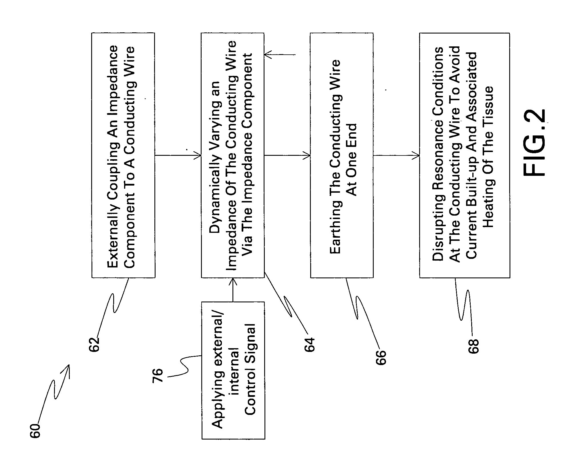
[0013] It is frequently desirable to place conducting structures in a magnet resonance (MR) scanner, such as ECG and pacemaker leads, catheter guide wires, and MR tracking devices for catheters. Such wire-like structures interact with the radio-frequency fields in the scanner, and under certain conditions can support large electrical currents and / or voltages and fields that can cause dangerous local heating in tissue. Aspects of the present technique provide alternative ways to keep these currents and / or voltages low by interfering with the resonant conditions that lead to the large currents and / or voltages and electric fields.

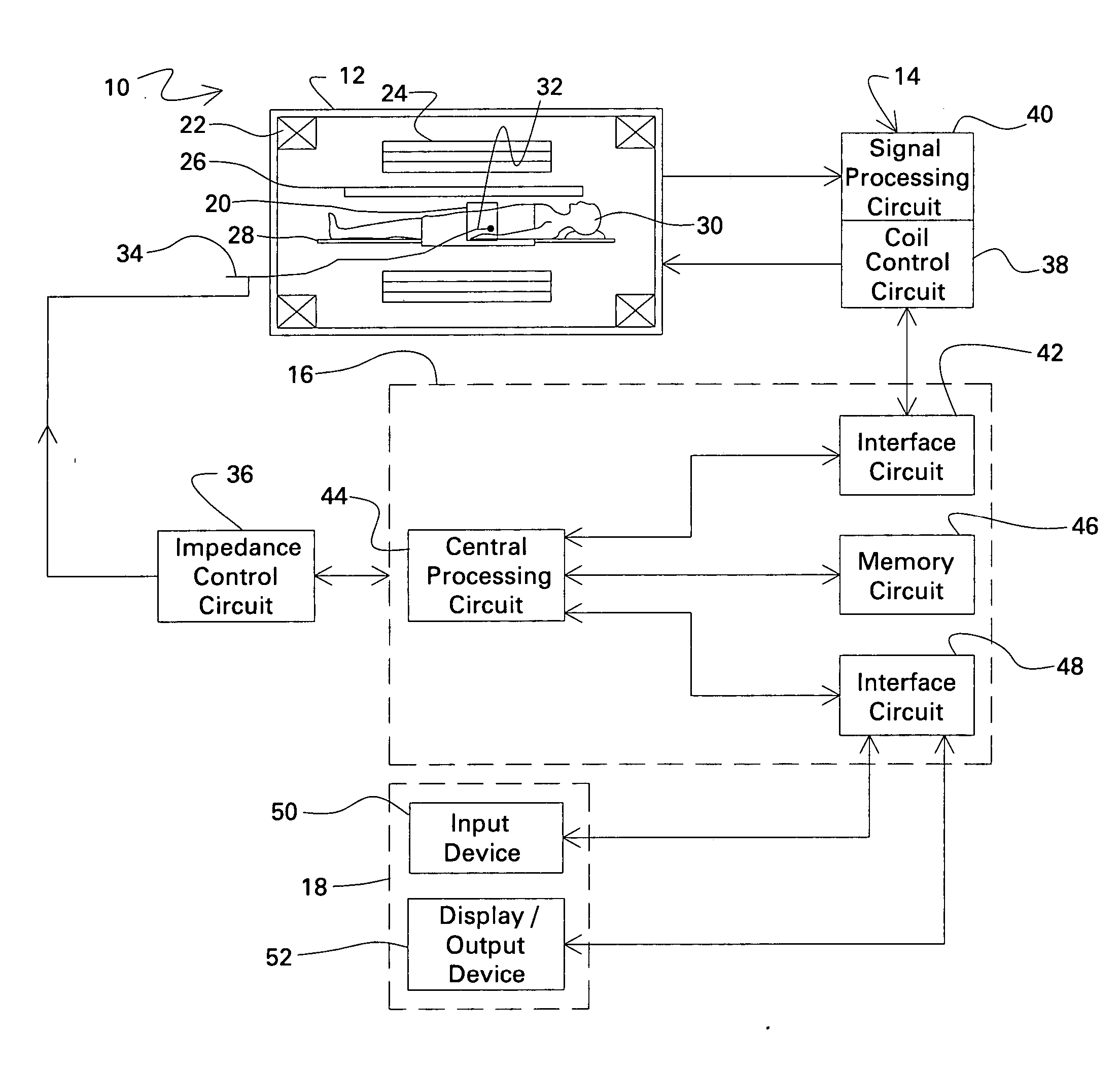
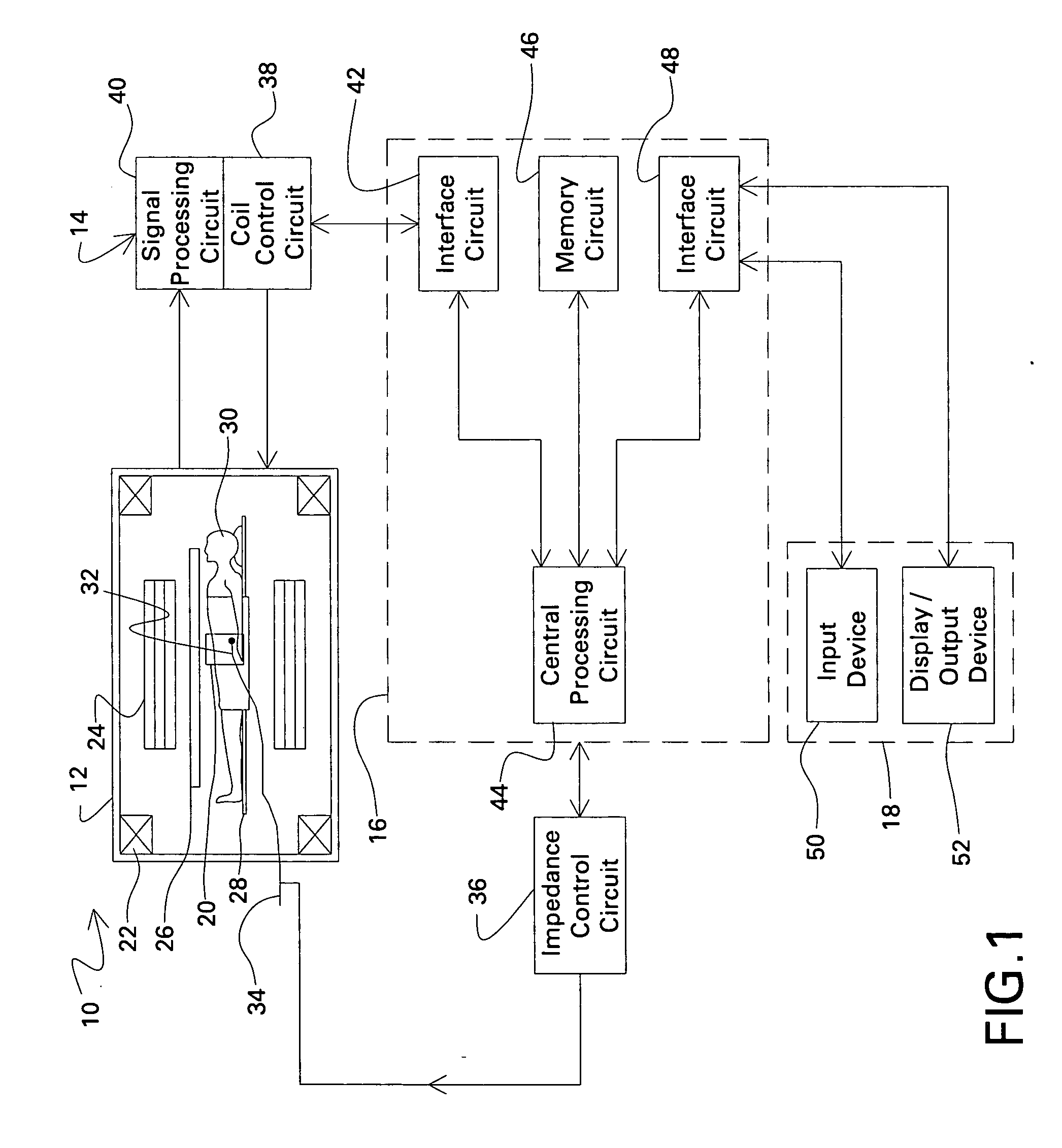
[0014] Referring now to FIG. 1, a magnetic resonance system, designated generally by the reference numeral 10, is illustrated as including a magnet assembly 12, a control and acquisition circuit 14, a system controller circuit 16, and an operator interface station 18. The magnet assembly 12, in turn, includes coil assemblies for selectively generating control...


PUM


Abstract

A conducting wire assembly (80) is provided for use with a magnetic resonance imaging (MRI) system (10). The conducting wire assembly (80) includes at least one impedance component (82) coupled externally to a conducting wire (34). The impedance component (82) is configured to dynamically vary an impedance of the conducting wire to disrupt resonant conditions of the conducting wire and to avoid current and / or voltage built-up on the wire and the associated heating of surrounding tissue.

Description

BACKGROUND [0001] The invention relates generally to interventional imaging, and in particular to systems and methods of reducing RF-induced heating in magnetic resonance imaging using invasive devices. [0002] In magnetic resonance (MR) imaging systems using invasive devices, large electrical currents and / or voltages may be created on long wire-like conducting structures of the invasive device, for example a catheter, placed in an MR scanner. A standing radio frequency (RF) wave is generated along the length of the conducting wire due to the resonant conditions that occur by the interaction of the conducting wire with RF fields of the imaging system. The resonant conditions lead to a built-up of large currents and / or voltages and potentially dangerous heating effects, both for the device and for the surrounding tissue. [0003] Typically choking circuits have been placed along the length of the wire to disrupt these large currents and / or voltages. Alternately, an electrically conducti...

Claims


Application Information

Patent Timeline
Patent Type & Authority Applications(United States)
IPC IPC(8): A61B5/05
CPCA61B5/055A61B2019/5251A61B2562/223G01R33/285G01R33/34084G01R33/3685A61B2034/2051
Inventor MALLOZZI, RICHARD PHILIPDUMOULIN, CHARLES LUCIANGROSS, PATRICK
Owner GENERAL ELECTRIC CO
Why Eureka
Try Eureka