
Efficiency booster circuit and technique for maximizing power point tracking

a technology of efficiency booster and power point tracking, applied in the direction of electric variable regulation, process and machine control, instruments, etc., can solve the problems of solar cell array not receiving enough sunlight to produce adequate power, etc., to prevent overcharging of electrical storage batteries, reduce voltage, and generate a considerable amount of energy

Inactive Publication Date: 2006-08-10
ISG TECH
View PDF13 Cites 445 Cited by
  • Summary
  • Abstract
  • Description
  • Claims
  • Application Information

AI Technical Summary

Benefits of technology

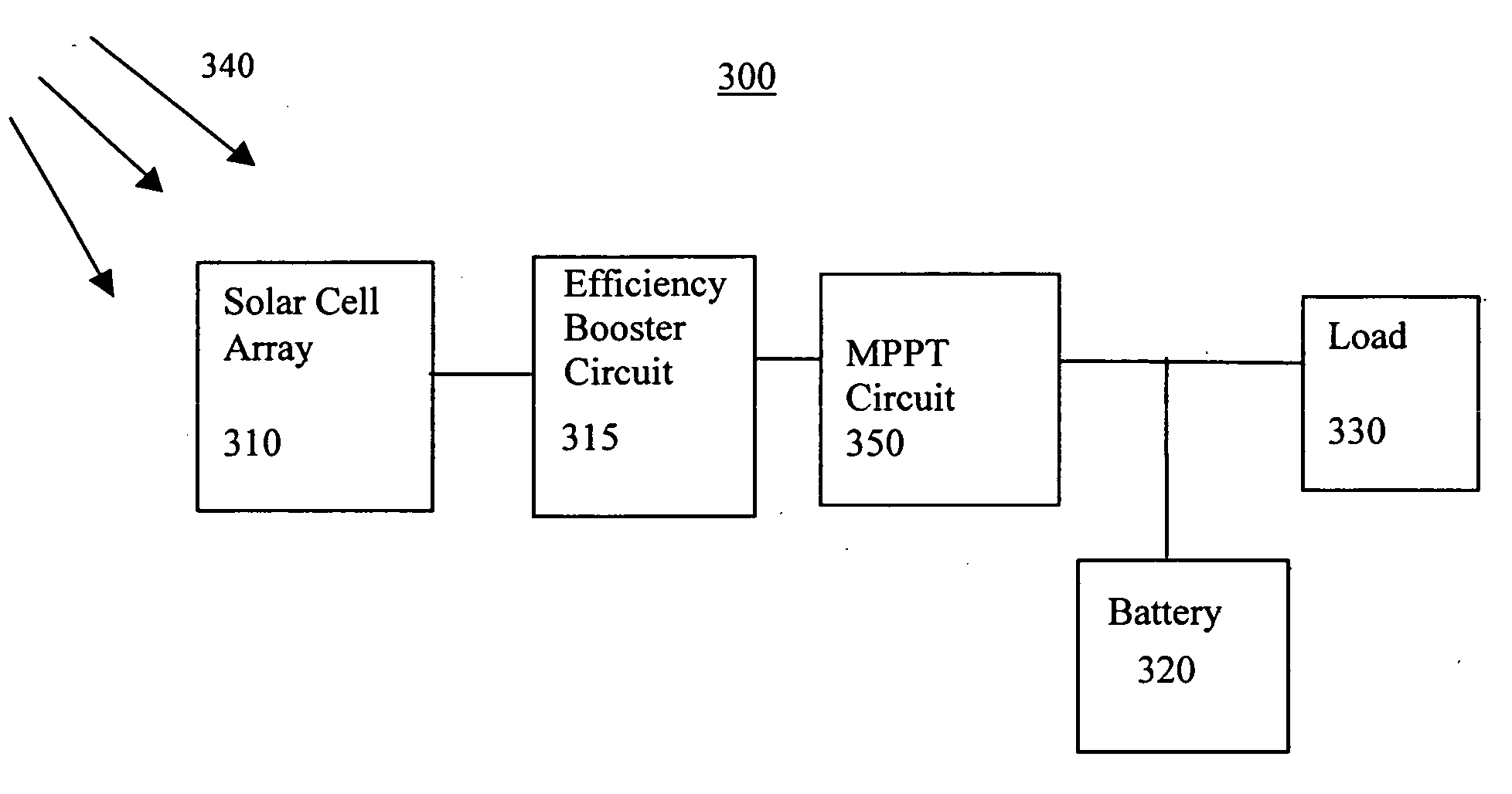
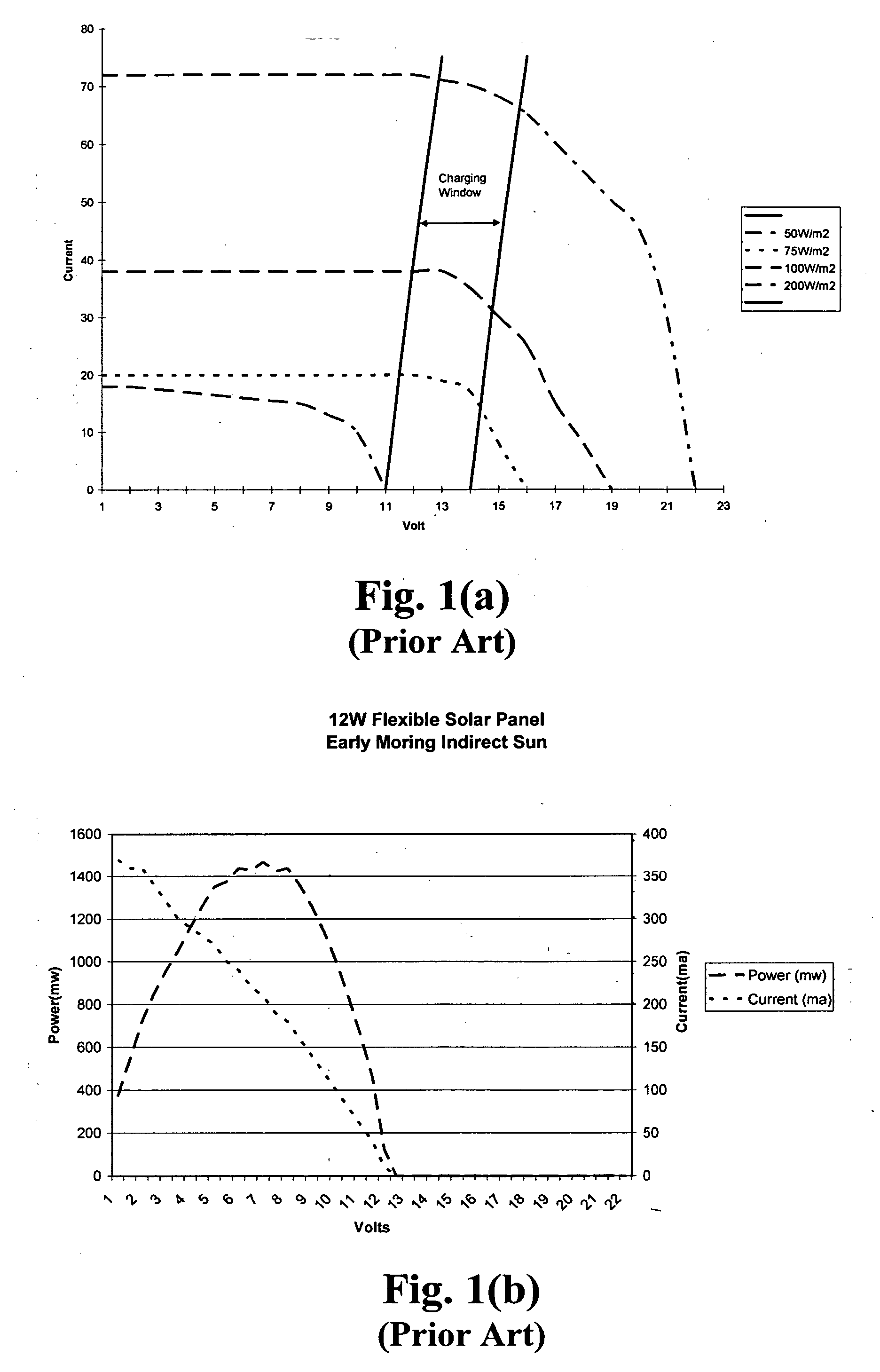
[0030] An advantage of the present invention it that it draws power from a solar cell array over a wider range of lighting conditions. A conventional solar cell array, which is typically designed to charge a 12 V battery, but is generating much lower voltages due to subdued sunlight illumination, still generates a considerable amount of energy. Although, under the conditions of subdued solar illumination, the amount of power generated may be small, the present invention results in a power increase sufficient over time to charge the electrical storage battery. For such a low power scenario, a conventional device takes much longer to charge the battery if it did so at all.
[0031] An advantage of the present invention is that it uses a switch mode power conversion to dynamically modify the load based on the available power generated by the solar cell device achieving an operational point defined as the Maximum Possible Power Generated (MPPG) point. Still another advantage of the present invention is the ability, by means of a feed back loop, to prevent overcharging of an electrical storage battery in the system.

Problems solved by technology

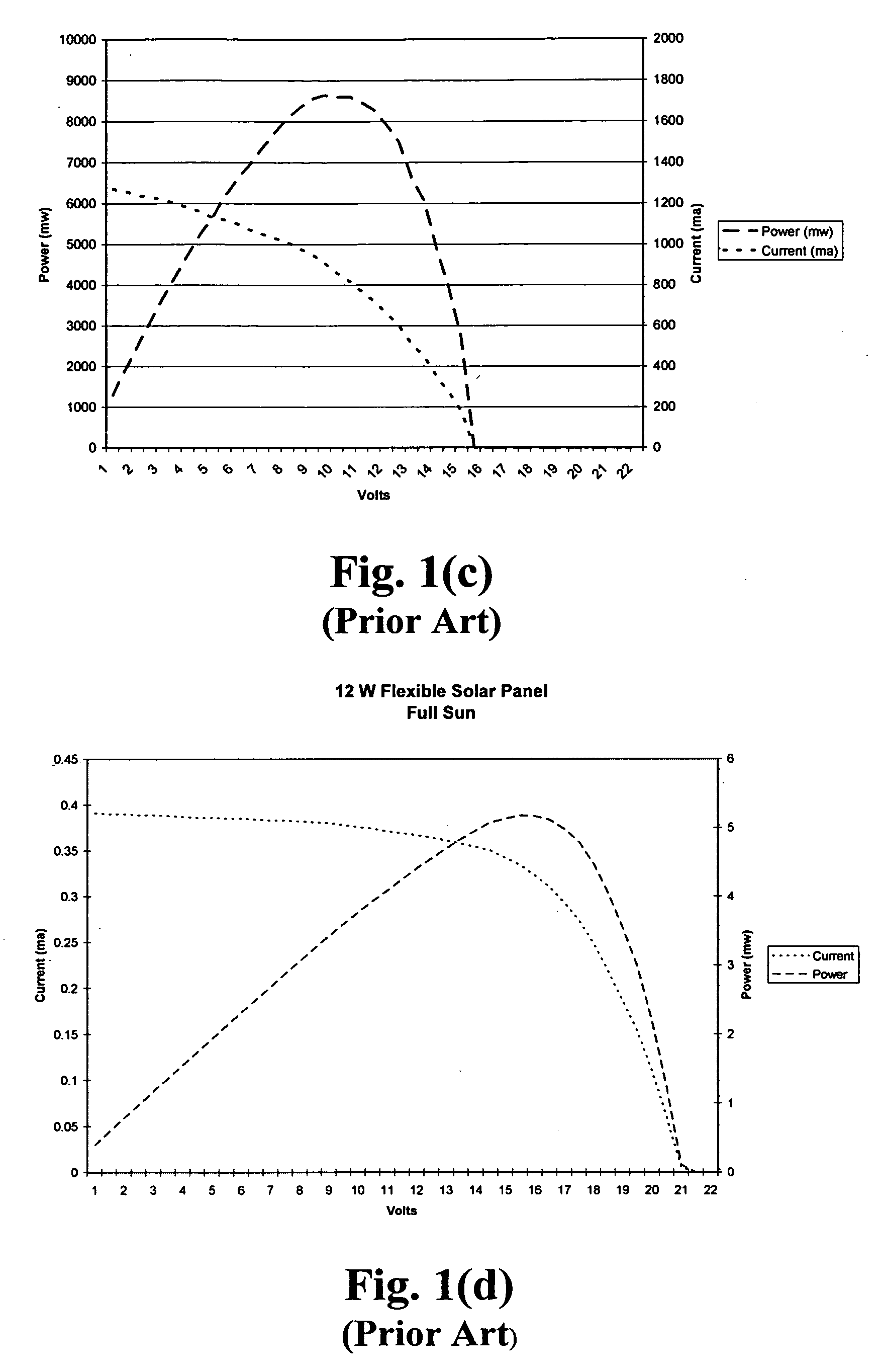
Under reduced incident solar radiation, a solar cell array does not receive enough sunlight to produce adequate power to charge an energy storage battery or to power a typical electrical load.

Method used


Image

  • Efficiency booster circuit and technique for maximizing power point tracking
  • Efficiency booster circuit and technique for maximizing power point tracking
  • Efficiency booster circuit and technique for maximizing power point tracking

Examples


Embodiment Construction

[0051] Further features and advantages of the invention, as well as the structure and operation of various embodiments of the invention, are described in detail below with reference to the accompanying FIGS. 2-17, wherein like reference numerals refer to like elements. The embodiments of the invention are described in the context of solar power and solar cells. Nonetheless, one of ordinary skill in the art readily recognizes that any photovoltaic device is encompassed by the embodiments of this invention as are other variable electrical power sources such as, but not limited to wind, geothermal, biomass, fuel cells and hydroelectric power sources.

[0052] Solar cell arrays are an excellent source of power since they can be operated anywhere under sunlight. However, improving the efficiency of the solar cell array is a major concern since solar cell arrays do not normally operate well under low light conditions. Specifically, since almost all solar cell arrays come with a rechargeable...


PUM


Abstract

The present invention provides an efficiency booster circuit and accompanying switch mode power conversion technique to efficiently capture the power generated from a solar cell array that would normally have been lost, for example, under reduced incident solar radiation. In an embodiment of the invention, the efficiency booster circuit generates an output current from the solar cell power source using a switch mode power converter. A control loop is closed around the input voltage to the converter circuit and not around the output voltage. The output voltage is allowed to float, being clamped by the loading conditions. If the outputs from multiple units are tied together, the currents will sum. If the output(s) are connected to a battery, the battery's potential will clamp the voltage during charge. This technique allows all solar cells in an array that are producing power and connected in parallel to work at their peak efficiency.

Description

CROSS-REFERENCE TO RELATED APPLICATION [0001] The present invention claims priority under 35 U.S.C. § 119(e) to U.S. Provisional Patent Application No. 60 / 640,071, entitled “Improving Maximum Power Point Tracking by Voltage Booster Circuit,” and filed on Nov. 29, 2004, the disclosure of which is hereby incorporated by reference in its entirety.BACKGROUND OF INVENTION [0002] 1. Field of Invention [0003] The present invention relates generally to electrical power systems and more particularly, to an efficiency booster circuit for increasing the output power efficiency of a variable power source, such as a solar cell. [0004] 2. Description of Related Art [0005] Solar power is a clean and renewable source of energy that has mass market appeal. Among its many uses, solar power can be used to convert the energy from the sun either directly or indirectly into electricity. The photovoltaic cell is a device for converting sunlight energy directly into electricity. When photovoltaic cells are...

Claims


Application Information

Patent Timeline
Patent Type & Authority Applications(United States)
IPC IPC(8): H01L31/042
CPCG05F1/67H01L31/02021H02J7/35Y02E10/58Y02E10/56
Inventor MATAN, STEFAN
Owner ISG TECH
Learn More