Method and device for the laser machining of workpieces

a laser machining and workpiece technology, applied in laser beam welding apparatus, welding apparatus, metal-working apparatus, etc., can solve the problems of high mechanical load on the manipulator, limited effort, velocity level, etc., and achieve the effect of better and higher-performance laser machining techniqu

Inactive Publication Date: 2006-08-10
KUKA SYSTEMS
View PDF19 Cites 31 Cited by
  • Summary
  • Abstract
  • Description
  • Claims
  • Application Information

AI Technical Summary

Benefits of technology

[0005] The object of the present invention is to provide a better and higher-performance laser machining technique.

Problems solved by technology

However, these efforts are limited by the relatively low velocity of welding, especially because the manipulator must perform acceleration and deceleration operations with its axes during the transport phases and the velocity level is also limited hereby.
Moreover, such acceleration and deceleration operations lead to higher mechanical loads on the manipulator.

Method used


Image

  • Method and device for the laser machining of workpieces
  • Method and device for the laser machining of workpieces
  • Method and device for the laser machining of workpieces

Examples


Embodiment Construction

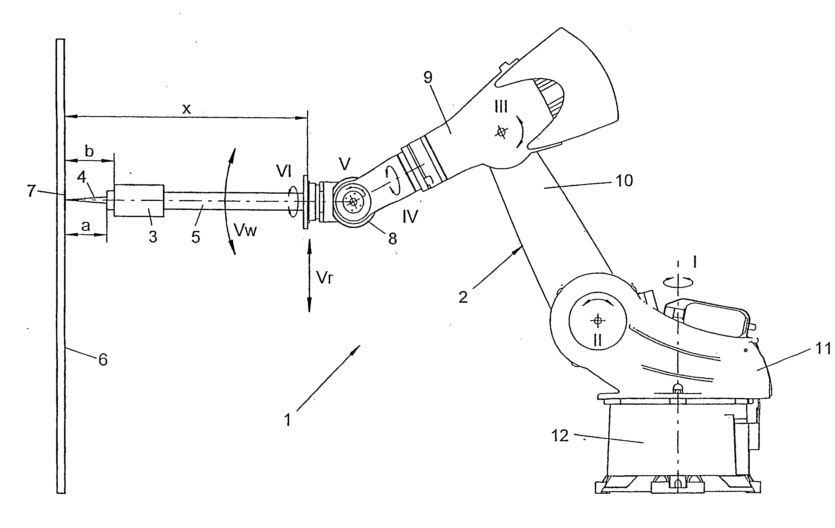
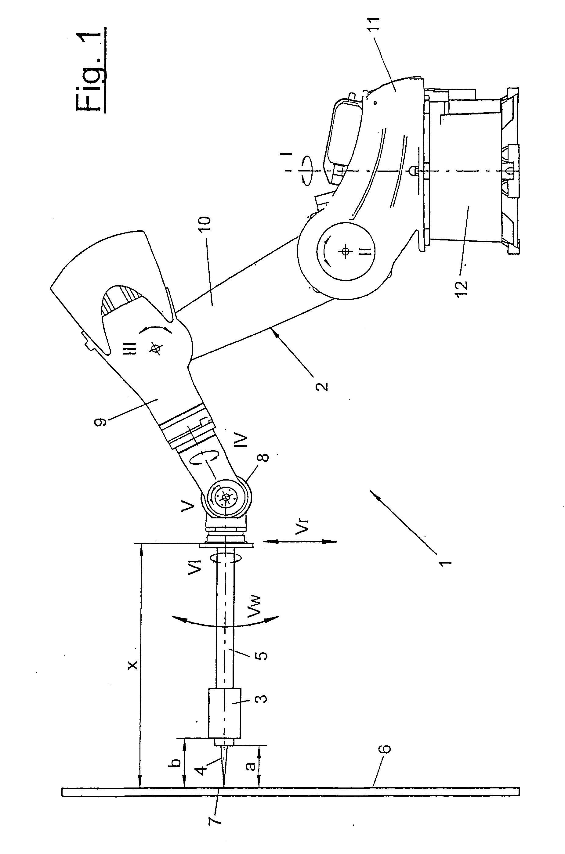
[0026] Referring to the drawings in particular, FIGS. 1, 8 and 10 show different variants of a laser machining device (1), which comprises at least one multiaxial mechanical manipulator (2) and a laser tool (3), which emits at least one laser beam (4) towards a workpiece (6).

[0027] The manipulator (2) is preferably designed as an at least six-axis articulated arm robot. In the embodiment being shown, it comprises a base (12), on which a bracket (11) is mounted rotatably about a first, vertical axis of rotation I, a rocker (10) being in turn mounted pivotably about a horizontal pivot axis II on the bracket (11). A robot arm (9) is mounted pivotably about another horizontal pivot axis III at the upper end of the rocker, and a three-axis robot hand (8) with three intersecting hand axes IV, V and VI being arranged at the front end of the robot arm (9). At the front end, the robot hand (8) has a rotatable driven flange (14), on which the laser tool (3) is mounted.

[0028] The laser tool ...


PUM

PropertyMeasurementUnit
focal distanceaaaaaaaaaa
anglesaaaaaaaaaa

Abstract

A method for machining workpieces (6) uses a moving laser beam (4), whereby the laser tool (3) is held at a separation above the workpiece (6) by means of a multi-axis mechanical manipulator (2) with a manipulator hand (8) and moved along a given track in an offset movement. During the machining process an at least partly opposing compensation movement of the laser beam (4) is superimposed on the offset movement. A device is provided for machining workpieces (6) with a moving laser beam (4). The laser tool (3) is held by means of a multi-axis mechanical manipulator (2) and a device for generation of a opposing compensation movement of the laser beam (4) is superimposed on the offset movement.

Description

CROSS REFERENCE TO RELATED APPLICATIONS [0001] This application is a United States National Phase application of International Application PCT / EP2004 / 008104 filed Jul. 20, 2004 and claims the benefit of priority under 35 U.S.C. § 119 of German Patent Application DE 103 33 456.4 filed Jul. 22, 2003, the entire contents of which are incorporated herein by reference.FIELD OF THE INVENTION [0002] The present invention pertains to a process and a device for the laser machining of workpieces BACKGROUND OF THE INVENTION [0003] It is known from practice that different types of machining of a workpiece, e.g., welding, cutting, engraving, heating or the like, can be carried out with a laser tool. The laser tools are moved in relation to the workpiece by means of multiaxial mechanical manipulators, e.g., compound tables, multiaxial articulated-arm robots or the like. During laser welding, the laser tool is usually guided by means of a pressing element in contact with and at a constant distance...

Claims


Application Information

Patent Timeline
Patent Type & Authority Applications(United States)
IPC IPC(8): B23K26/08B23K26/20B23K26/10
CPCB23K26/0807B23K26/0884B23K26/246B23K26/082B23K26/244
Inventor RIPPL, PETER
Owner KUKA SYSTEMS
Why Eureka
Try Eureka