Wire bonding method

Inactive Publication Date: 2006-08-10
SHINKAWA CO LTD
View PDF6 Cites 45 Cited by
  • Summary
  • Abstract
  • Description
  • Claims
  • Application Information

AI Technical Summary

Benefits of technology

[0005] The object of the present invention is to provide a wire bonding method that provides a further or improved low-loop implementation.
[0027] In addition, in the present invention, since the bent part is bonded directly to the bump, the loop height at the first bond point can be made lower, and low wire loop implementation is effected.
[0028] On the other hand in the present invention, the wire is bonded to the bump directly as a second bond point, the loop height at the second bond point can be made lower, and low wire loop implementation is effected. Furthermore, the bent part is bonded to the interconnect wiring that is the first bond point to first form a lower first bonding part, and then the wire is bent and superimposed onto that lower first bonding part to form an upper first bonding part. Accordingly, the reliability of the bonding strength to the interconnect wiring is significantly enhanced.
[0029] Furthermore, in the present invention, the bent part is formed, when cutting the wire from the bump, by moving the capillary parallel to the interconnect wiring and the bump to be connected next and then toward the interconnect wiring that is the second bond point; as a result, the direction of the bent part of the wire tip end can be bent in a direction suitable for the next bonding, and, in conjunction therewith, the shape of the wire loop for bonding that bent part to the interconnect wiring that is the second bond point, after bonding it to the bump, can be made lower. For this reason also, low wire loop implementation can be effected.
[0030] In the present invention, since the upper surface of the bump is flat, the wire connected to this bump can be substantially horizontal, and low wire loop implementation is effected.
[0031] In the present invention, the ball is mashed when forming the bump until the thickness is such that tearing-off occurs from the lower part of the ball neck portion when the wire is pulled; accordingly, the bump height is extremely low, the loop height on the pad can be made even lower, and further low wire loop implementation is effected.

Problems solved by technology

For that reason, it would not be able to respond to the desire for low-loop implementation.
However, since it is necessary to superimpose wire, doubled, on the pressure-bond ball, there have been inherent limitations to low-loop implementation.

Method used


Image

  • Wire bonding method
  • Wire bonding method
  • Wire bonding method

Examples


first embodiment

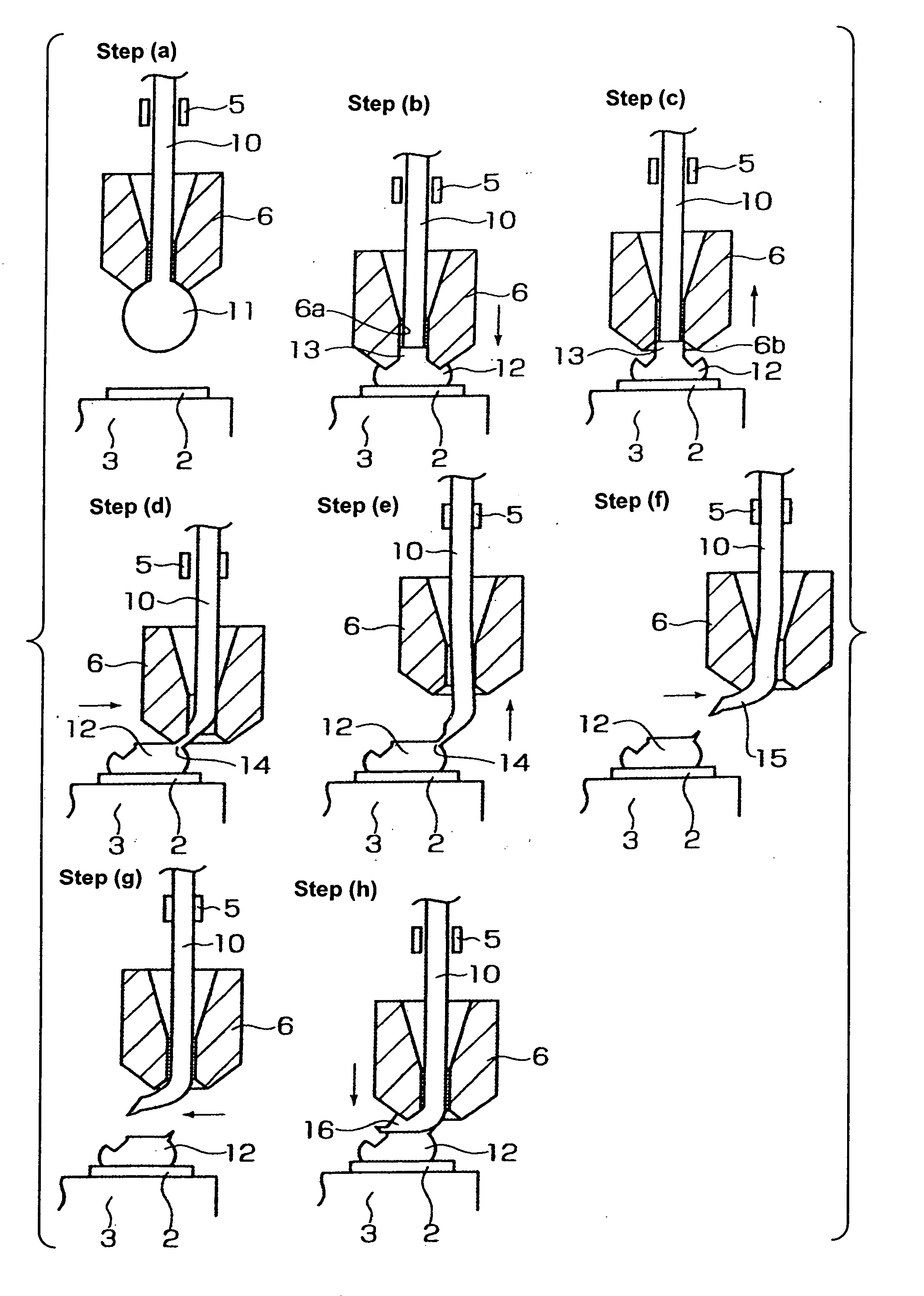
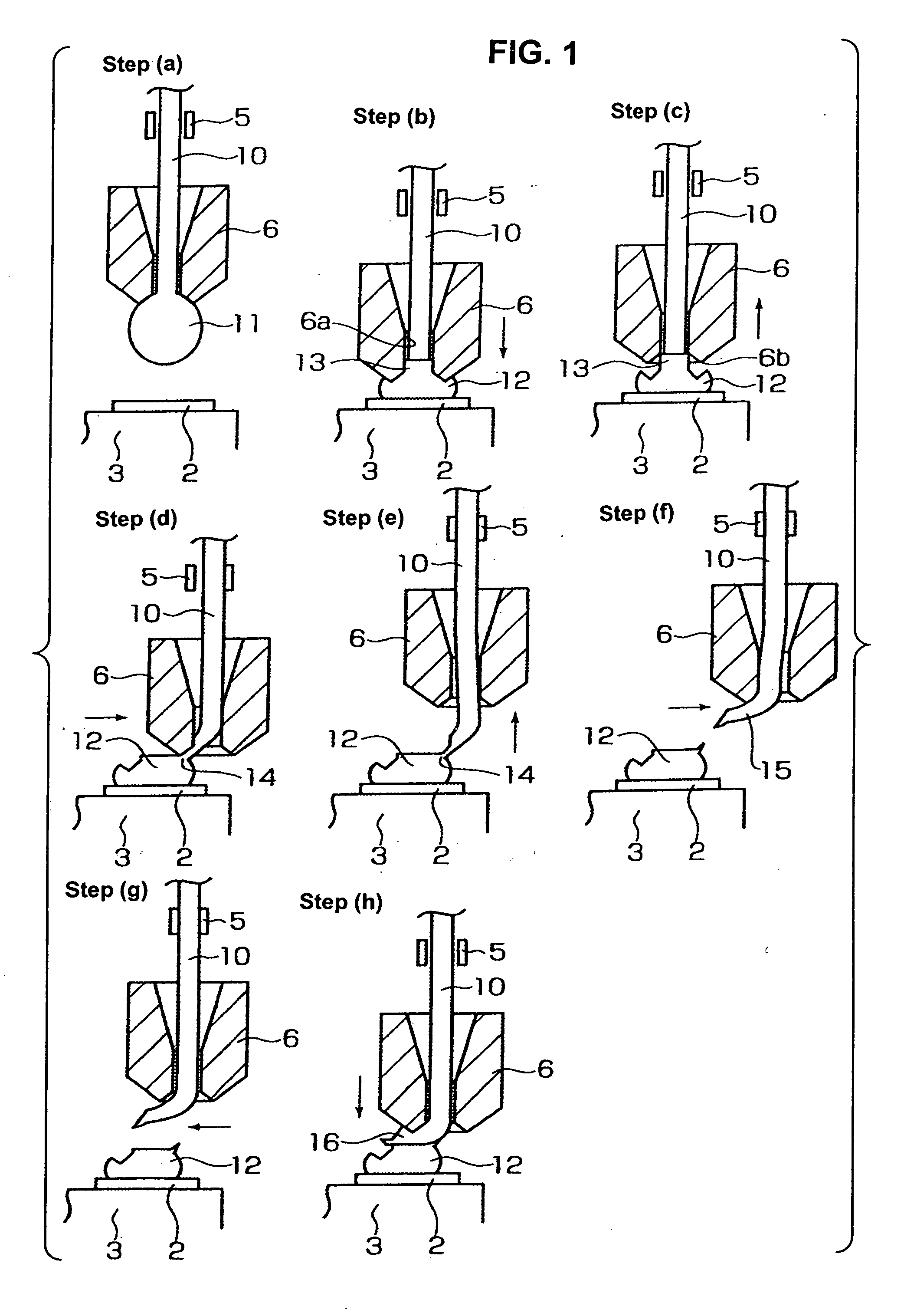
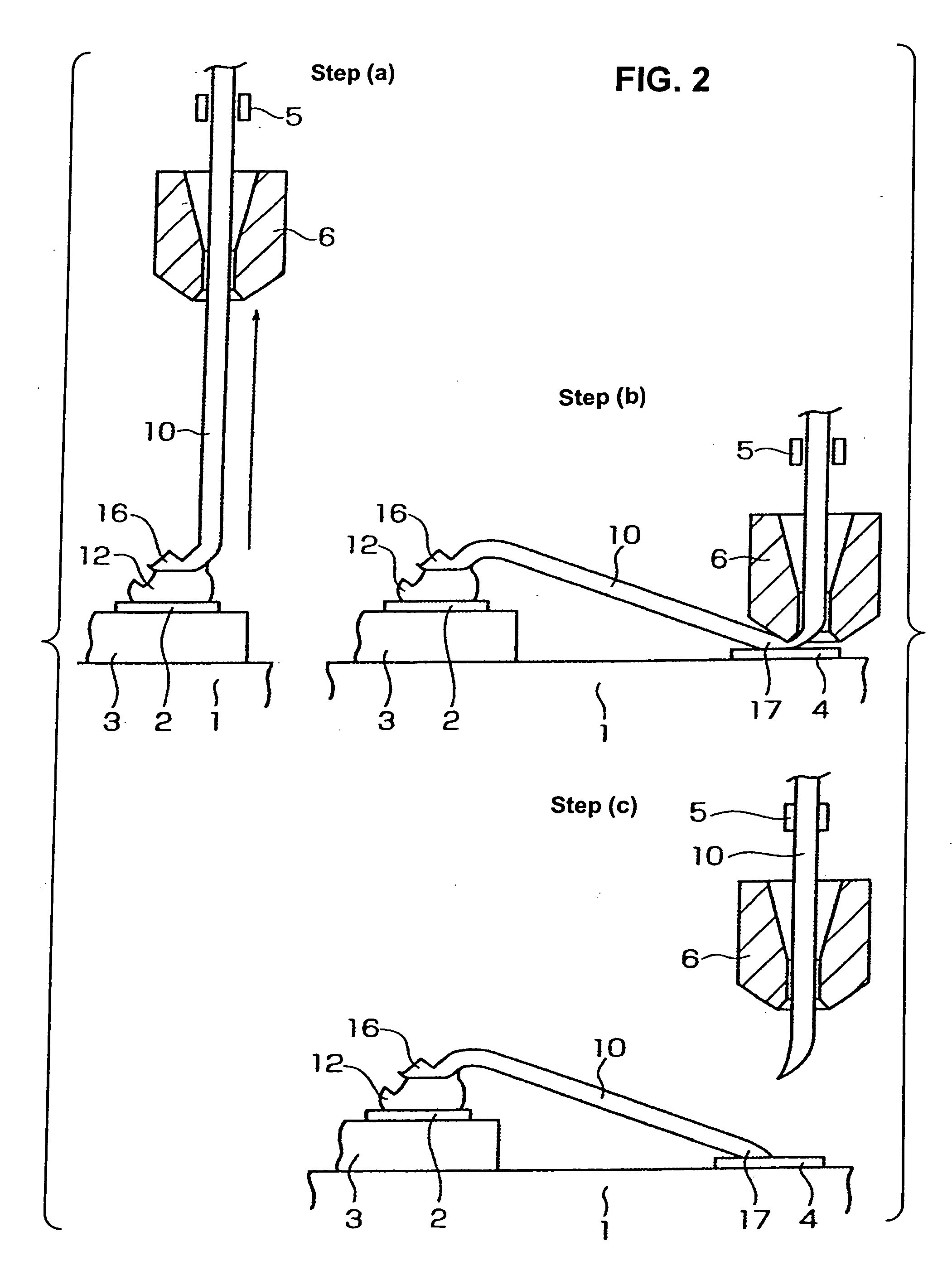
[0040] the wire bonding method of the present invention is described with reference to FIG. 1 and FIG. 2. As shown in FIG. 2, a die 3 on which a pad 2 of a die (or “die pad”) is formed is mounted on a circuit board 1 comprising a ceramic substrate or print board or lead frame or the like. An interconnect wiring (or an outer lead or conductive pathways) 4 is formed on the circuit board 1.

[0041] First, in step (a), a ball 11 is formed by an electric torch (not shown in the drawing) at the tip end of a wire 10 passed through a damper 5 and inserted through a capillary 6, after which the damper 5 is in an open condition.

[0042] Next, in step (b), the capillary 6 descends (or lowered) and bonds the ball 11 to the pad 2 that is the first bond point. Thereby, a portion of the ball 11 bulges up into the through-hole 6a in the capillary 6, and a pillar portion 13 is formed on a bump 12.

[0043] Following the step (b), in step (c), the capillary 6 is raised so that the edge 6b at the lower end...

second embodiment

[0054] In the second embodiment, after the step (f) shown in FIG. 1 where the bump forming process is completed, the capillary 6 is moved upward from the interconnect wiring 4 in step (a) of FIG. 3.

[0055] Next, in step (b), the damper 5 closes, the capillary 6 descends, bonds the bent part 15 to the interconnect wiring 4 that is the first bond point, and forms a lower first bonding part 20. Also, the damper 5 is brought in an open condition.

[0056] Next, in step (c), the capillary 6 is raised, and then is moved above the lower first bonding part 20 in step (d).

[0057] In the next step (e), the damper closes, the capillary 6 is lowered, the wire portion 21 shown in the illustration for step (d) is bent, and the wire portion 21 is bonded onto the lower part first bond point, forming an upper first bonding part 22, thus making it a first bonding part 3 and completing the first bonding process.

[0058] After the step (e), the wire 10 is connected onto the bump 12 formed on the pad 2 that...

fourth embodiment

[0070] More specifically, in the fourth embodiment, after the step (d) of FIG. 5, the damper 5 opens, and the capillary 6 is moved in step (a) shown in FIG. 7 to above the interconnect wiring 4.

[0071] Then, in step (b), the capillary 6 descends, bonds the bent part 15 to the interconnect wiring 4 that is the first bond point, and forms the lower first bonding part 20.

[0072] Next, in step (c), the capillary 6 is raised, and in step (d), the capillary 6 is moved above the lower first bonding part 20.

[0073] In the next step (e), the capillary 6 is lowered, the wire portion 21 show in the illustration for step (d) is bent, the wire portion 21 is bonded onto the lower first bonding part 20, whereupon the upper first bonding part 22 is formed, and that is made the first bonding part 23.

[0074] After the step (d), the wire 10 is connected onto the bump 12 formed on the pad 2 that is the second bond point. More specifically, in step (f) shown in FIG. 7, the capillary 6 ascends and moves i...


PUM

PropertyMeasurementUnit
Thicknessaaaaaaaaaa
Heightaaaaaaaaaa

Abstract

A wire bonding method with the process of performing a first bonding to a pad of a die that is a first bond point, and the process of performing a second bonding to an interconnect wiring (or a lead) that is a second bond point, thus connecting the pad and the interconnect wiring with a wire. A bump is first formed on a pad, and, in a wire cutting step performed during the step of forming the bump, the wire protruding from the tip end of a capillary is bent in the lateral direction to form a bent part, and then the bent part is bonded to the bump, thus completing the first bonding process; after which the wire is bonded to the interconnect wiring, thus completing the second bonding process.

Description

BACKGROUND OF THE INVENTION [0001] The present invention relates to a wire bonding method and more particularly to a wire bonding method well suited to low-loop implementation. [0002] In wire bonding methods for bonding a ball to a first bond point, the ball neck portion at a tip end of a bonding wire becomes a recrystallized area which is hard and brittle; accordingly, in order to form a wire loop, the wire must be bent from the portion above the recrystallized area. For that reason, it would not be able to respond to the desire for low-loop implementation. [0003] Japanese Patent Application Laid-Open (Kokai) Nos. H9-51011 and 2004-172477 solve the above-described problems. The methods disclosed in these publications takes the following steps: a ball formed at the tip end of a wire is first bonded to a die pad to form a compression-bond ball; next, after raising the capillary, it is moved in a direction opposite from an interconnect wiring (or an outer lead of a lead frame); then, ...

Claims


Application Information

Patent Timeline
IPC IPC(8): B23K31/02
CPCB23K20/004B23K20/007B23K2201/42H01L24/48H01L24/78H01L24/85H01L2224/05599H01L2224/48091H01L2224/48095H01L2224/48227H01L2224/48455H01L2224/48471H01L2224/48472H01L2224/48479H01L2224/49425H01L2224/78301H01L2224/85051H01L2224/85181H01L2224/85186H01L2224/85399H01L2224/85951H01L2224/85986H01L2924/01004H01L2924/01005H01L2924/01082H01L2924/00014H01L2924/01006H01L2924/01033H01L2224/45099H01L2924/00B23K2101/42H01L24/49H01L2924/15787H01L2224/4554H01L23/48
Inventor MII, TATSUNARITOYAMA, TOSHIHIKOTEI, SHINSUKE
Owner SHINKAWA CO LTD
Why Eureka
Try Eureka