Non-inductive electric power generation all-in-one machine and electric vehicle

A technology for electric power generation and electric vehicles, applied in electric vehicles, motors, electric components, etc., can solve problems such as efficiency reduction, conversion efficiency limitation, adverse effects, etc. adverse effects

Active Publication Date: 2021-06-25
刘贵平
View PDF10 Cites 0 Cited by
  • Summary
  • Abstract
  • Description
  • Claims
  • Application Information

AI Technical Summary

Problems solved by technology

This problem of the motor causes a lot of electric energy to be wasted in vain; this disadvantage is even greater in electric vehicles, the speed of electric vehicles is constantly changing, and the rated speed and torque of electric vehicle motors are designed for driving on flat roads. When the electric vehicle is running at low speed or at high speed on the highway, its efficiency will be greatly reduced, resulting in a decrease in the efficiency of converting electrical energy into kinetic energy;
[0004] The above-mentioned problems of existing motors, due to the magnetization curve characteristics of ferromagnetic materials and the existence of magnetic domain loss, in electric vehicles, even if the current input to the coil in the motor is 4.5-5 times higher than that of driving on a flat road, its output However, the torque cannot be increased proportionally, and the conversion efficiency between electric energy and kinetic energy is limited, which also has an adverse effect on the battery life of the electric storage unit.

Method used


Image

  • Non-inductive electric power generation all-in-one machine and electric vehicle
  • Non-inductive electric power generation all-in-one machine and electric vehicle
  • Non-inductive electric power generation all-in-one machine and electric vehicle

Examples


Embodiment 1

[0058] This embodiment relates to an ineffective electric generator to provide a new motor based on the law of ridiculum, which helps to minimize the alternating magnetic field and magnetization curve characteristics of motor coils on the energy conversion efficiency of motor energy.

[0059] The inductive electric power generation unit includes a housing, and a spindle that is rotatable relative to the housing, the unusual electric power generator further comprising a ring magnetic field formed within the housing, several forming a coil and a control unit set. Among them, the ring magnetic field is formed in the housing in the housing by the spindle, and the magnetic field direction of the annular magnetic field is located in the radial direction of the spindle, and the annular magnetic field is configured to be distributed and the magnetic field direction is opposite. Each of the coils is partially in a ring magnetic field; the two coils in the same group are arranged in paralle...

Embodiment 2

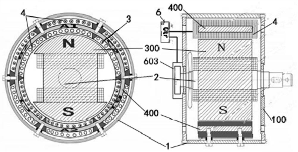
[0081] In this embodiment, an exemplary structure, such as an unusual electric power generation unit, such as an inductive electric power generator in the form of another configuration. Figure 5 As shown in the present embodiment, the inductive electric generator is used with a DC power source or provides a DC power generation, and is fixed by the housing 1, the internal spindle 2 is in the form of inner rotor in the housing 1.

[0082] In this inner rotor structure, the magnet 300 is a permanent magnet or electromagnet, and the two parts of the magnet 300 are formed between the two poles and the annular core 400 of the magnet 300 respectively form two parts of the annular magnetic field 3. One magnet 300 is disposed inside the annular core 400, and two magnetic poles of the magnet 300 can form the magnetic field direction of the magnetic field 3 between the magnet 300 and the annular core 400 in terms of two portions.

[0083] Of course, the magnet 300 can use a permanent magnet ...

Embodiment 3

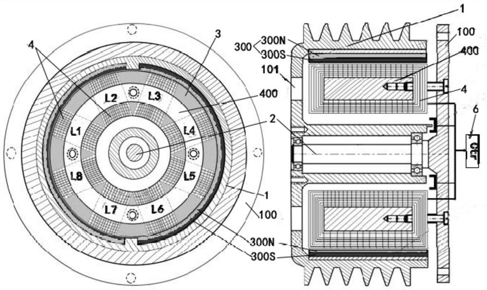
[0086] This embodiment relates to an ineffected electric power generator suitable for three-phase AC electric fields, and an exemplary structure is Figure 6 with Figure 7 As shown, in the present embodiment, the unusual motor generator is driven by a three-phase AC power source, or provides a three-phase AC power supply; in the same, it can employ the inner rotor or the outer rotor.

[0087] Such as Figure 6 As shown, the spindle 2 is fixed, and the housing 1 is rotated to the spindle 2, and the outer rotor form is formed. Two semi-circular magnets 300 are fixed to the housing 1, and the annular magnetic field 3 is formed around the annular core 400. Among them, the magnet 300 uses a permanent magnet. The entire structure form and examples of embodiments.

[0088] Such as Figure 7 As shown, the housing 1 is fixed, and the internal spindle 2 is rotated relative to the housing 1, and the inner rotor form is formed. The magnet 300 is disposed inside the annular core 400, which can be...


PUM


Abstract

The invention provides a non-inductive electric power generation all-in-one machine and an electric vehicle. The non-inductive electric power generation all-in-one machine comprises a shell, a main shaft, an annular magnetic field formed in the shell, a plurality of groups of coils arranged in pairs and a control unit. The magnetic field direction of the annular magnetic field is located in the radial direction of the main shaft, and the annular magnetic field is configured into two parts which are equally distributed around the main shaft and opposite in magnetic field direction. Each turn of circuit in the coils partially passes through the annular magnetic field, and the two coils in the same group are arranged in parallel, are wound reversely, are distributed in a central symmetry manner by taking the main shaft as the center, and respectively pass through two parts of the annular magnetic field. And the control unit controls the current commutation of one group of coils or the on-off of a plurality of groups of coil circuits. And the annular magnetic field and the coil are fixedly arranged on one of the shell and the main shaft respectively. The non-inductive electric power generation all-in-one machine is arranged based on the Lenz's law, and can weaken the adverse effect of the alternating magnetic field and magnetization curve characteristics of the motor coil on the energy conversion efficiency of the motor.

Description

Technical field [0001] The present invention relates to the field of motor technology, and more particularly to an ineffective electric generator. The invention also relates to an electric vehicle. Background technique [0002] At present, whether it is an electric motor or a generator, the coil is embedded in the iron core teeth, and the iron core dental circle generates an alternating magnetic field to generate the rotational driving force of the motor, or the rotation of the generator. The resulting magnetic field cuts and generates an electric force in the coil. The alternating magnetic field generates magnetic domain loss and eddy current loss. Moreover, in the DC permanent magnet motor, since the equalization of the tooth distribution is deviated, there is also a torque loss of the tooth groove, which greatly reduces the efficiency of the motor or generator. [0003] In addition, the magnetic field strength increase or decrease in the electromagnetized core and the current ...

Claims


Application Information

Patent Timeline
Patent Type & Authority Applications(China)
IPC IPC(8): H02K29/00H02K1/06H02K11/01
CPCH02K29/00H02K1/06H02K11/01H02K2201/00Y02T10/64
Inventor 刘贵平
Owner 刘贵平
Why Eureka
Try Eureka