Active combine rotor deceleration
- Summary
- Abstract
- Description
- Claims
- Application Information
AI Technical Summary
Benefits of technology
Problems solved by technology
Method used
Image
Examples
Embodiment Construction
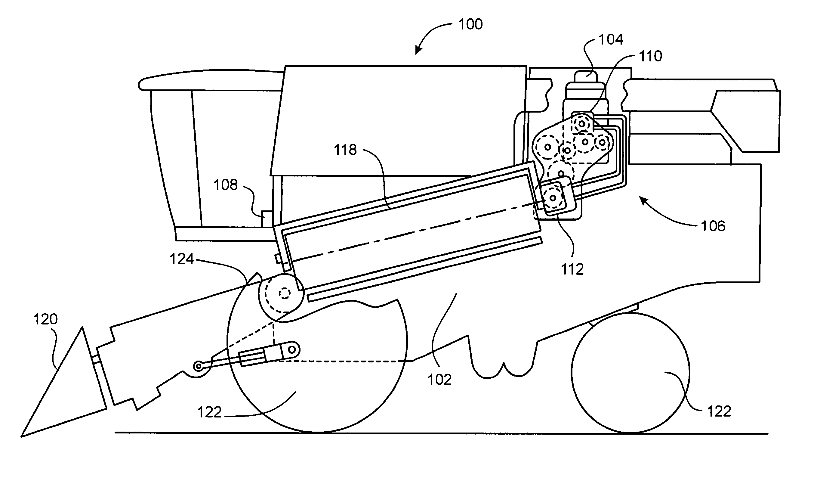
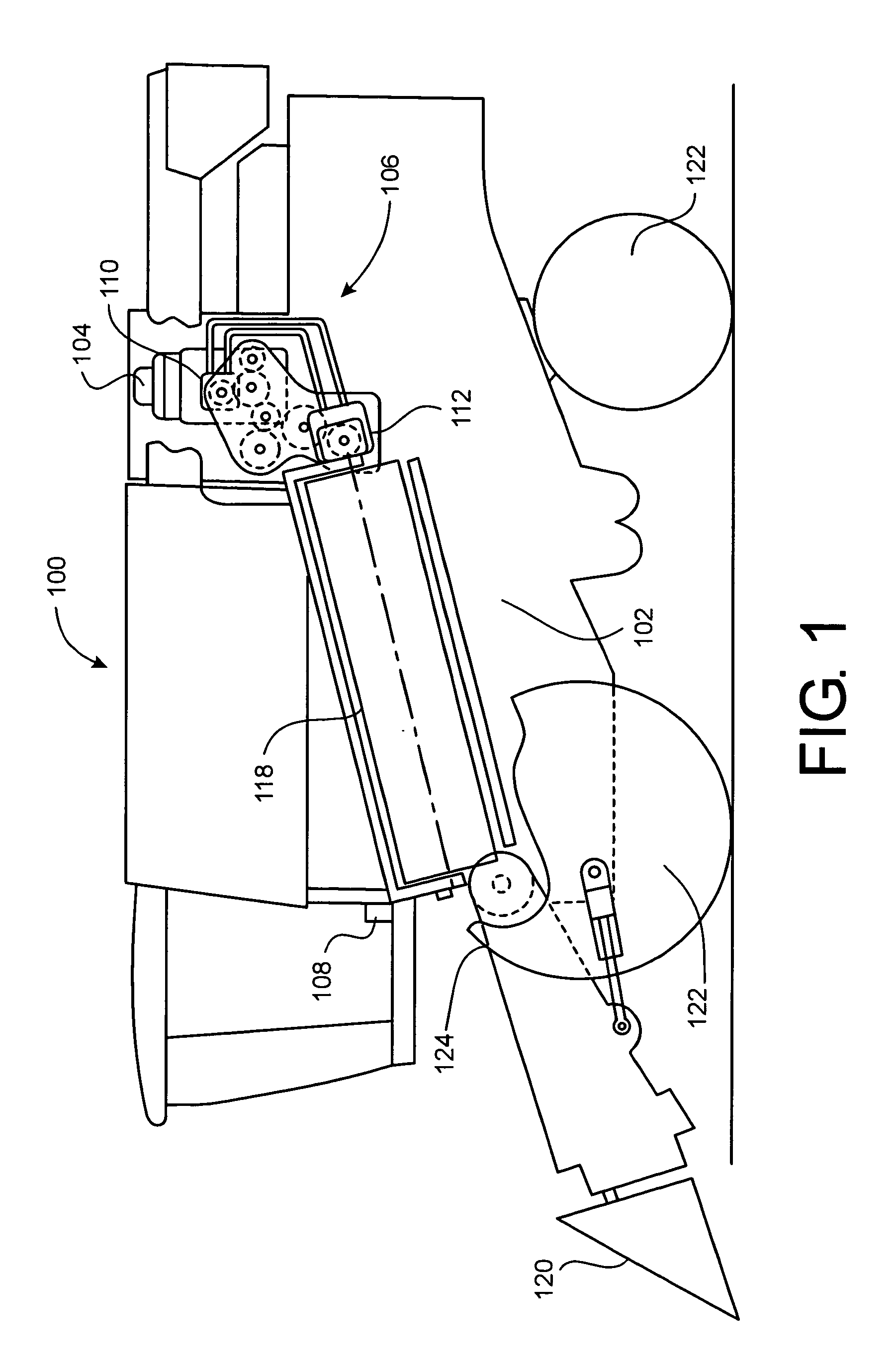
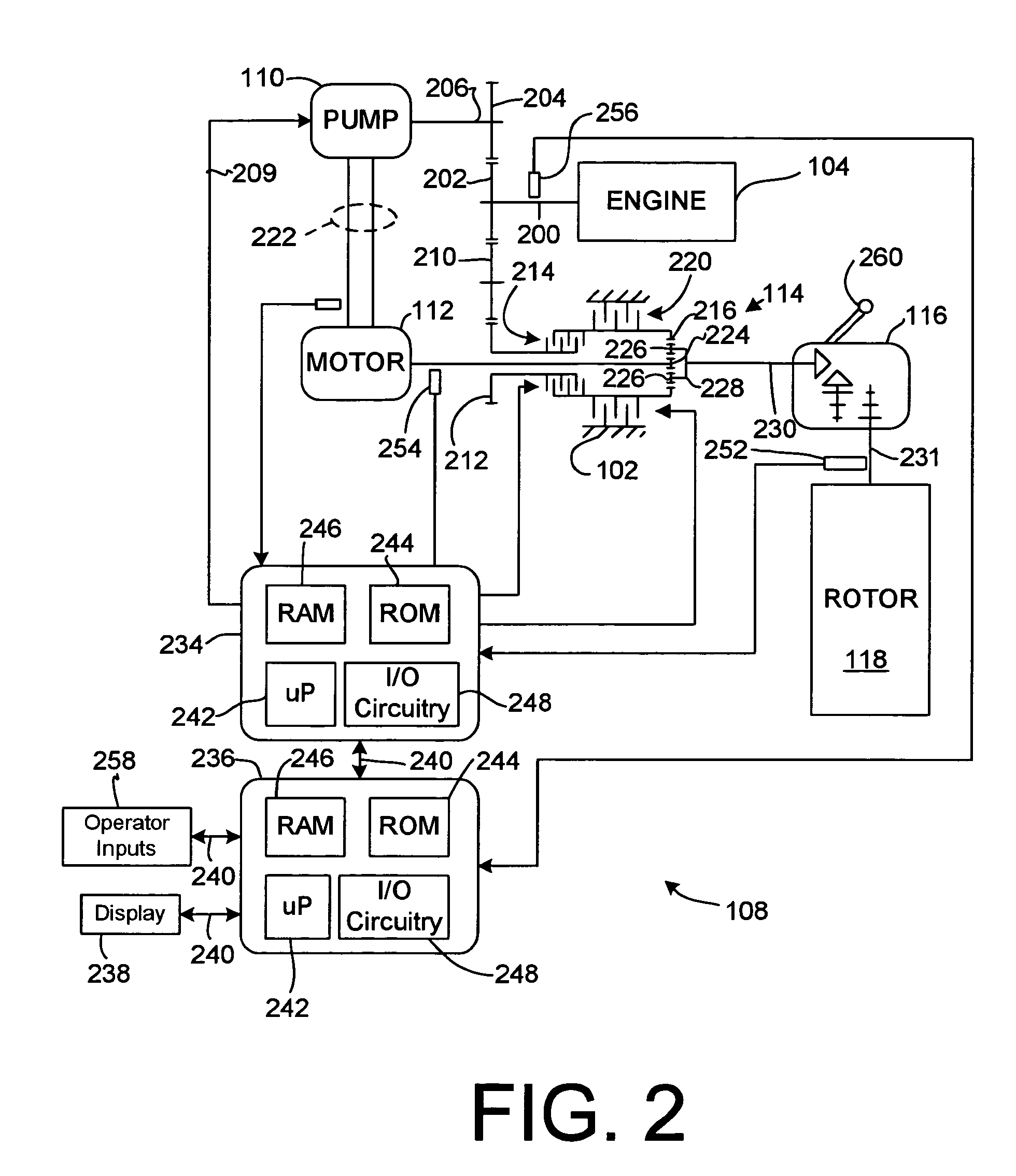
[0027] Referring to FIGS. 1 and 2, a work vehicle is illustrated, here shown as an agricultural combine 100. The work vehicle has a chassis 102 on which an engine 104 is mounted. A drive system 106 is coupled to and driven by engine 104 to rotate rotor 118. An electronic control system 108 is coupled to the engine and the drive system to monitor various sensors, to control the engine and to control the drive system.
[0028] The engine 104 is preferably an internal combustion engine, such as a multi-cylinder gasoline or diesel engine.
[0029] The drive system 106 includes a hydraulic pump 110 that is coupled to and driven by the engine, a hydraulic motor 112 that is fluidly coupled to and driven by pump 110, gear trains coupling engine 104 to the pump, engine 104 to a planetary gear arrangement, the planetary gear arrangement itself, and a gearbox driven by the planetary gear arrangement that, in turn, drives the combine rotor 118.
[0030] Rotor 118 rotates with respect to chassis 102 a...
PUM
 Abstract
Description
Claims
Application Information
 - R&D
- Intellectual Property
- Life Sciences
- Materials
- Tech Scout
- Unparalleled Data Quality
- Higher Quality Content
- 60% Fewer Hallucinations
Browse by: Latest US Patents, China's latest patents, Technical Efficacy Thesaurus, Application Domain, Technology Topic, Popular Technical Reports.
© 2025 PatSnap. All rights reserved.Legal|Privacy policy|Modern Slavery Act Transparency Statement|Sitemap|About US| Contact US: help@patsnap.com


