Wide range continuous diluter

a diluter and wide-range technology, applied in the direction of instruments, specific gravity measurement, mechanical means, etc., can solve the problems of inaccurate characterization of emissions, low dilution ratio, and low dilution range of dilution systems employing typical traditional partial flow diluters, so as to reduce the residence time of the flow, reduce the loss of small particles, and reduce the effect of dilution ratio

Active Publication Date: 2006-08-17
HORIBA LTD
View PDF0 Cites 16 Cited by
  • Summary
  • Abstract
  • Description
  • Claims
  • Application Information

AI Technical Summary

Benefits of technology

[0015] In another aspect of the invention, to minimize the small particle losses at high dilution ratio, the invention comprehends using a by-pass flow upstream of the orifice flow meter to reduce the residence time of the flow in the transfer line.

Problems solved by technology

As the dilution ratio increases, the accuracy of the calculated dilution ratio drops due to the uncertainties of the total flow and dilution air flow measurements.
This results in inaccurate characterization of the emissions.
Therefore, use of dilution systems employing the typical traditional partial flow diluter has been limited to somewhat lower dilution ranges, such as 40:1 or lower.

Method used


Image

  • Wide range continuous diluter
  • Wide range continuous diluter
  • Wide range continuous diluter

Examples


Embodiment Construction

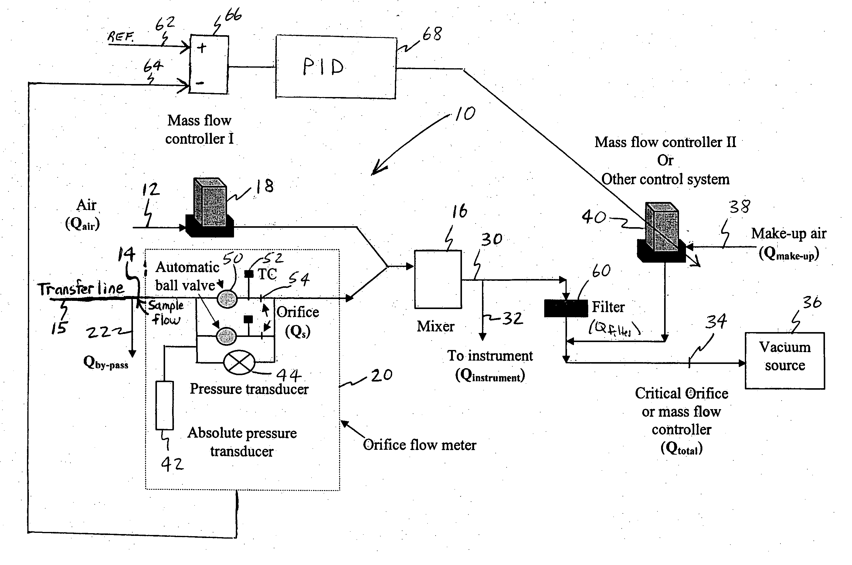
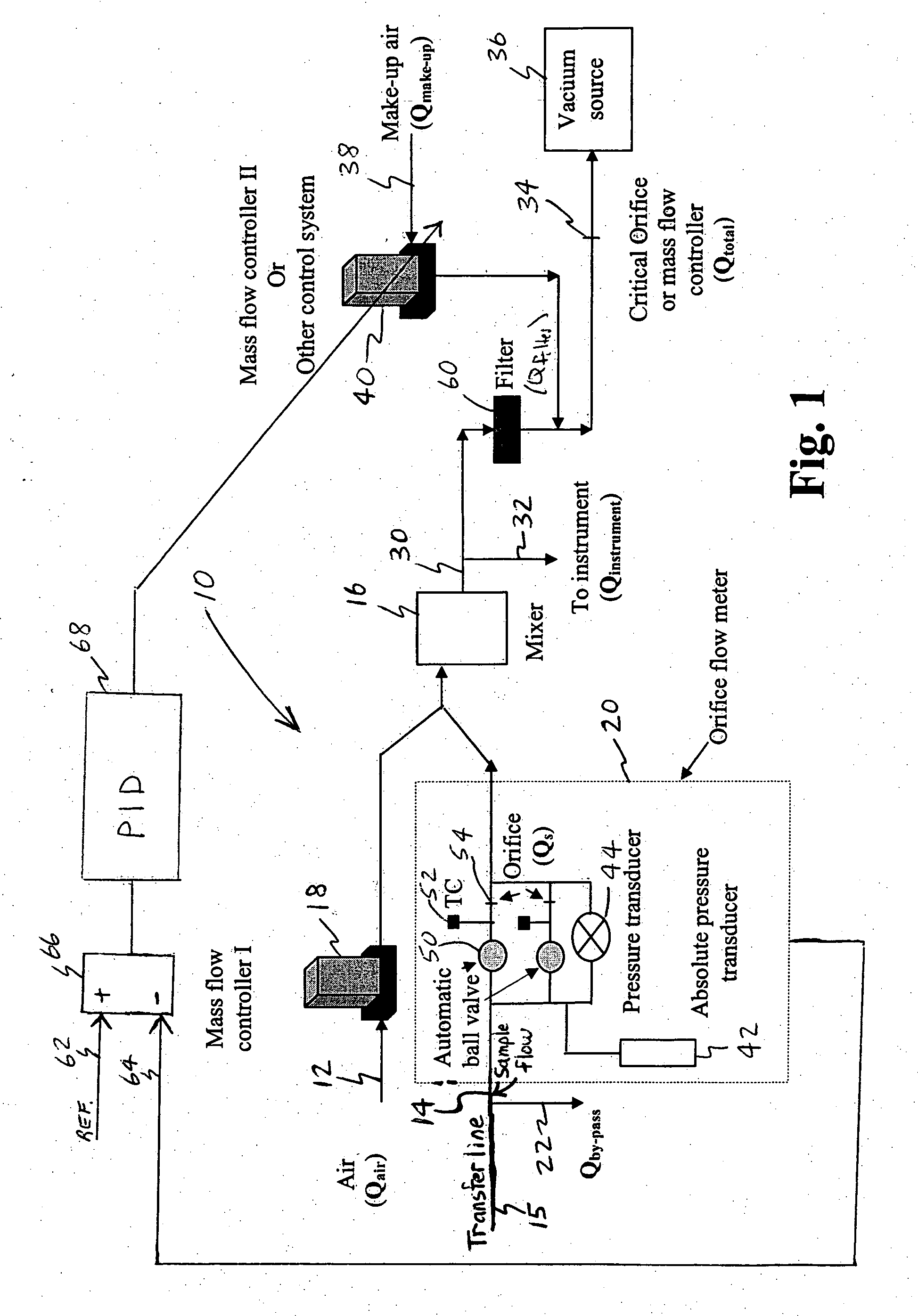
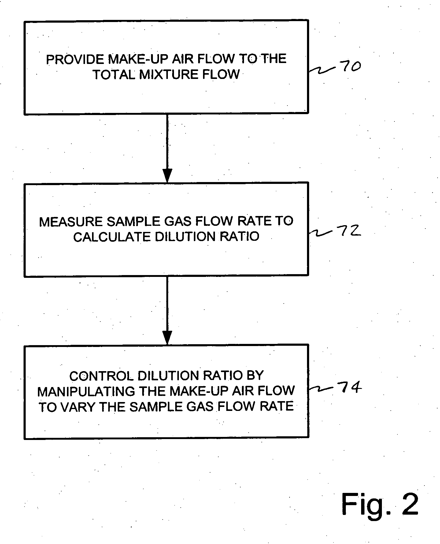
[0018] In FIG. 1, the preferred embodiment of the wide range continuous diluter is generally indicated at 10. A dilution gas inlet 12 receives a dilution gas, and a sample gas inlet 14 receives a sample gas. A mixer 16 is connected to dilution gas inlet 12 and sample gas inlet 14 for receiving and mixing the gases at a dilution ratio. The flow rate of the dilution gas is controlled by mass flow controller 18. Orifice flow meter 20 measures the sample gas flow rate. By-pass flow outlet 22 is provided upstream of flow meter 20 to reduce the residence time of the sample gas flow through the transfer line 15, which connects inlet 14 to the expected sampling source, for example, engine exhaust.

[0019] Mixer 16 has outlet 30, and instrument flow outlet 32 is arranged to provide a well-defined flow into the instrument. The gas mixture flows at a controlled rate provided by critical orifice 34 and vacuum source 36. Critical orifice 34 may alternatively be a mass flow controller. Make-up gas...


PUM

PropertyMeasurementUnit
flow rateaaaaaaaaaa
gas flow rateaaaaaaaaaa
residence timeaaaaaaaaaa

Abstract

A wide range continuous diluter for diluting gases that contain small particles to allow subsequent measurement of the diluted gases with an instrument is provided. A dilution gas inlet receives a dilution gas, and a sample gas inlet receives a sample gas. A flow meter measures the sample gas flow rate. A mixer receives and mixes the dilution gas and the sample gas at a dilution ratio. An instrument flow outlet provides a well-defined flow into the instrument from the mixture flow. A make-up gas inlet is arranged to provide make-up gas into the mixture flow at a controlled rate. Because the dilution gas flows at a controlled rate and the mixture flows at a controlled rate, changing the flow rate of the make-up gas causes a responsive change in the sample gas flow rate, thereby allowing continuous adjustment and control of the dilution ratio when desired.

Description

BACKGROUND OF THE INVENTION [0001] 1. Field of the Invention [0002] The invention relates to diluting engine exhaust or other gases that contain small particles. [0003] 2. Background Art [0004] In order to characterize engine exhaust particulate matter (PM) emissions, it is required that the engine exhaust be diluted. Because the engine emits a high concentration of particles, the engine exhaust must be diluted with a high dilution ratio (typically greater than 100:1) to reach the measurable range of certain particle number instruments. The number concentration of engine exhaust particles may vary in a wide range. This is due to the variety of engine technologies and operating conditions. To satisfy these requirements and obtain accurate results, wide range dilution capability is required. [0005] The typical traditional partial flow diluter controls dilution air flow and total mixture flow with mass flow controllers. The sample flow is calculated by subtracting the dilution air flow...

Claims


Application Information

Patent Timeline
Patent Type & Authority Applications(United States)
IPC IPC(8): G01N1/38
CPCG01N1/2247G01N1/2252G01N1/38G01N2001/2264G01N1/00G01N1/22
Inventor WEI, QIANG
Owner HORIBA LTD
Why Eureka
Try Eureka