
Integrated Membrane Sensor

a technology of electromagnetic effect field and membrane sensor, which is applied in the measurement of magnetic beads labelled molecules, magnetic property measurements, instruments, etc., can solve the problems of slowed commercialization, no disposable multiplexed assays on the market, and no examples of integrating electromagnetic effect field microchips into membrane-based assay devices

Active Publication Date: 2008-08-21
DIAGNOSTIC BIOSENSORS
View PDF3 Cites 67 Cited by
  • Summary
  • Abstract
  • Description
  • Claims
  • Application Information

AI Technical Summary

Benefits of technology

[0039]It is often desirable to have many assays (multiplexed) performed in the same device, saving time and money. In an In-Vitro Diagnostic device, this means breaking up the single “test” and “control” bars across the strip into several discrete spots. Lateral flow strip technology appears to be ready to support multi-spot arrays, but there are no disposable multiplexed assays on the market.
[0042]Thus, integrating microchip technology directly into flow membrane technology is a novel invention that can provide a faster route to combining electronics with in-vitro diagnostics. The very low cost per sensor, in high volumes, enables disposable sensor electronics.
[0044]There are several advantages of integrated electromagnetic effect field detectors. The main one is vastly improved sensitivity and precision for measuring the location and amount of electromagnetic effect field labels in a given location in an assay membrane. As the size of spots shrinks, and their areal density increases, it becomes increasingly difficult (if not impossible) for a single large detector far away to resolve signals from an array of tiny spots. The challenges that must be addressed in order to bring integrated electromagnetic effect field detectors to market are related to the lack of a design for such a thing, and a lack of established manufacturing capability for both the microchip and assay flow structures. The invention in this disclosure addresses these challenges with novel structures and assembly procedures that result in an integrated microchip electromagnetic effect field detector that can be manufactured in a cost-effective way.
[0045]The present invention provides an integrated detection system for membrane-based disposable assay cartridges. The system uses disposable assay structures whose fluid sample handling is based on flow permeable membranes. Bibulous paper membranes are one kind of flow permeable membrane. Nitrocellulose, fiberglass, and nylon are two commonly used materials for flow permeable membranes. These membranes perform several functions including: providing a flow path through an otherwise solid structure, providing a solid matrix for depositing chemical reaction materials, acting as a filter for relatively large objects in the flow. Ideally the membrane has regular pore size, controlled and uniform flow rates, and well controlled surface chemistry of the solid matrix.

Problems solved by technology

Lateral flow strip technology appears to be ready to support multi-spot arrays, but there are no disposable multiplexed assays on the market.
However, the complexity of lab-on-a-chip systems, along with the immaturity of the manufacturing capabilities for them, has slowed their commercialization.
There are no examples of integrating electromagnetic effect field microchips into membrane-based assay devices.

Method used


Image

  • Integrated Membrane Sensor
  • Integrated Membrane Sensor
  • Integrated Membrane Sensor

Examples


Embodiment Construction

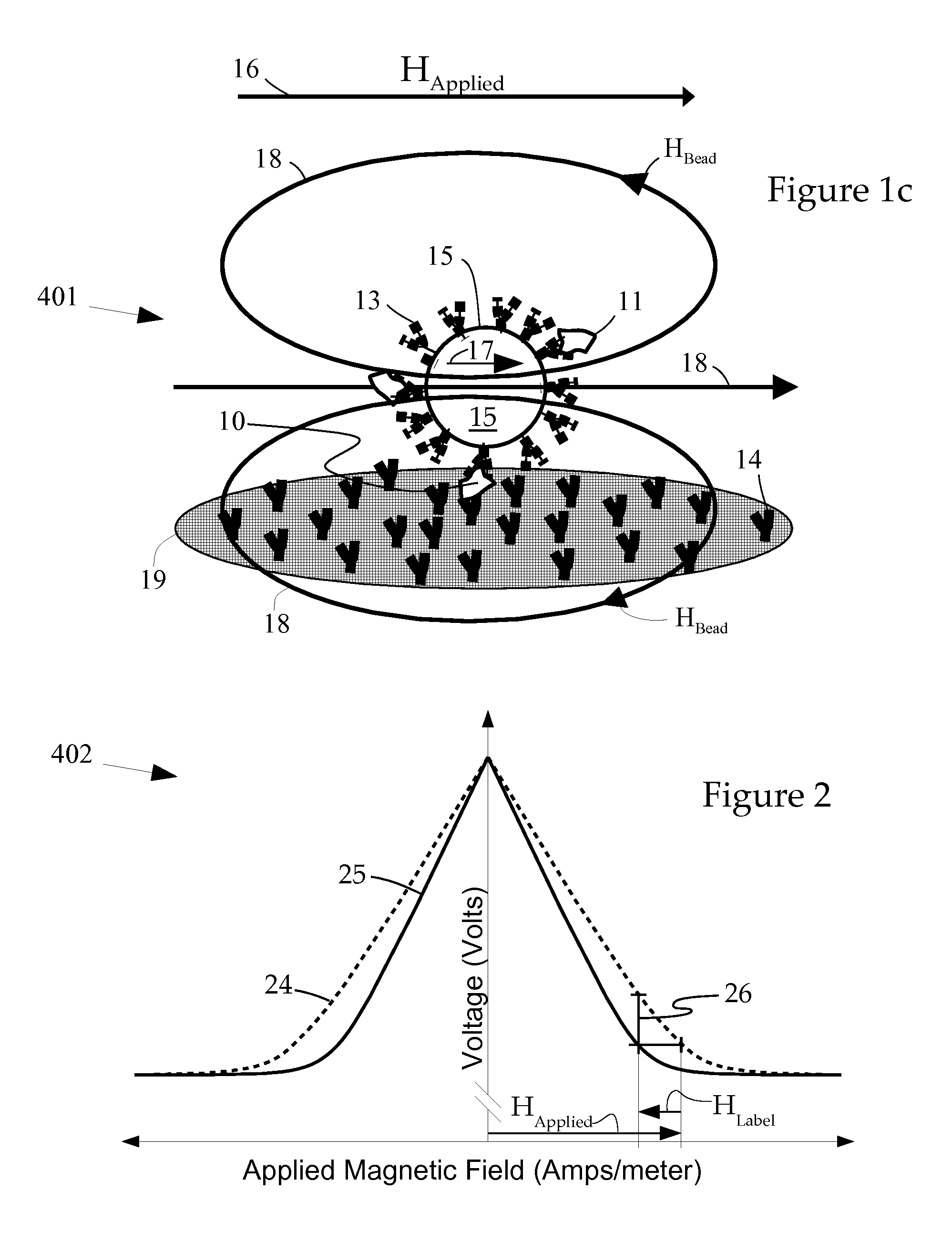
[0071]The purpose of the invention is to measure the quantity of bioanalyical material (analyte) in a given sample. An immunoassay is a common form of bioassay where the analyte is captured by antibodies. FIG. 1 shows an analyte molecule 10“sandwiched” between: one of the many capture antibodies, 14, on the sensor surface 19; and one of many “probe” antibodies, 13, on a paramagnetic label 15. Label 15 also has other antibodies, 11, captured on it, but not sandwiched. An applied magnetic field (HApplied), whose orientation is indicated by vector arrow 16, induces a linear increase in the magnitude of magnetization, M, in label 15. The orientation of M is indicated by vector arrow 17, it is always parallel to HApplied.

[0072]A Giant Magnetoresistive (GMR) detector 19 measures the total magnetic field along its axis of sensitivity which is the sum of HApplied and Hlabel, whose orientation in the region around the label is represented roughly by oval curves 18.

[0073]A commonly used form ...


PUM


Abstract

An integrated microelectronic sensor is provided in a disposable flow membrane sensing device. The integrated sensors detect electromagnetic effect labels in flow detection zones above the sensor in the membrane. The labels are small particles that give off a detectable electromagnetic signal. They are commonly used for isolating and quantifying biochemical targets of interest. The sensors are fabricated using planar integrated circuit technologies. Sensors can detect labels of several types including magnetic, electric, and photonic. These types all have in common the fact that the sensor detects the label at a distance. Magnetoresistive sensors for detecting magnetic labels, and photodiodes for detecting photonic labels are described.A system for using the sensors is described. There are disposable cartridges with a backing that supports the sensors and membrane is described. The integrated sensor in the cartridge is designed to be discarded after use. Also, label excitation sources are provided. The multi sensor array chip can be configured in order to detect labels in multiple zones, and to monitor progress of flow down a strip of membrane. These multiple label detection zones, using sandwich assay techniques, can quantify analyte concentration for many types of analytical samples. Also, the membrane can be micropatterned in order to provide multiple or unusually shaped flow paths.

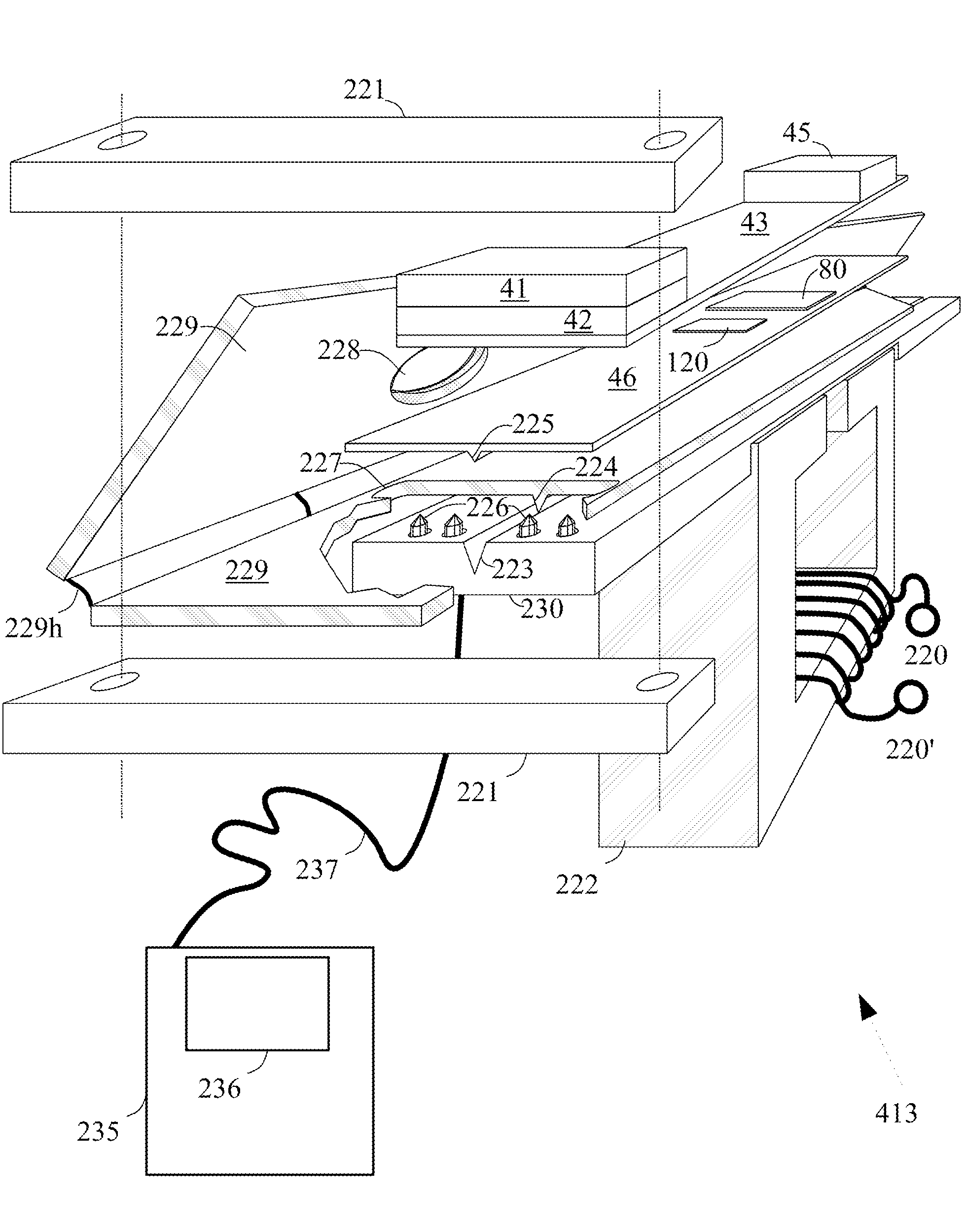
Description

BACKGROUND OF THE INVENTION[0001]The present invention describes novel devices and methods for detecting small labels using electronic sensors. Detecting the labels is of interest because they allow one to “see” or “quantify” tiny objects that would otherwise not be visible or detectable. For this to work, the labels must be “bound” to the object of interest. Or, sometimes, the labels are of interest in and of themselves. The object of interest could be a living cell or bacterium in the field of microbiology; a protein, nucleic acid, or antibody in the field of biochemistry; or almost any chemical species analyte.[0002]In any case, the labels are very small particles. Here a particle is defined as a small physical object, typically with a longest dimension less than 1 mm. Many particles are roughly spherical, though there are also oblate spheroids, needles, cubes, and all manner of three dimensional shapes. The word “bead” is sometimes used to mean a particle.[0003]A label is a spec...

Claims


Application Information

Patent Timeline
IPC IPC(8): G01N27/00G01R33/00
CPCG01R33/12G01N33/54373G01N27/4145G01R33/1269
Inventor TONDRA, MARK CHRISTOPHER
Owner DIAGNOSTIC BIOSENSORS
Learn More