Pressurizing device

Inactive Publication Date: 2006-08-17
KOGANEI +1
View PDF4 Cites 2 Cited by
  • Summary
  • Abstract
  • Description
  • Claims
  • Application Information

AI Technical Summary

Benefits of technology

[0018] When the rolling diaphragm is used, the following features can be further utilized. That is, hysteresis loss is remarkably small and life of the diaphragm is long since the folded portion rolls; the effective pressure-receiving area is kept constant throughout the entire stroke; the pressure device can be designed for minute pressure (water column: 25 mm) to high pressure (100 kg/cm2) since the folded portion is narrow; calculation of the pressure thrust can be simplified since there is no spring rigidity; no particular attention has to be paid to surface finishing, a material, and hardness, etc. of the reciprocating body or cylinder since the diaphragm rolls; and there is an automatic centripetal effect even when slight eccentricity or declination is caused in the reciprocating body (when the reciprocating body is moved to one side, a restoring force acts thereon and the reciprocating body is returned to a central line).
[0019] Since the

Problems solved by technology

When the object to be pressurized is intended to be subjected to a predetermined pressure thrust, the gravity and the friction resistance force working on the piston and the pressure rod become disturbance with respect to a target value and make it difficult to control the pressure thrust.
Particularly, in a pneumatic cylinder operated by lower pressure than that in a hydraulic cylinder, an influence of the friction resistance of the sealing member becomes relatively large and, as a result, it becomes difficult to control the pressure thrust with high accuracy.
In order to achie

Method used


Image

  • Pressurizing device
  • Pressurizing device
  • Pressurizing device

Examples


Example

[0032] Hereinafter, embodiments of the present invention will be detailed based on the drawings.

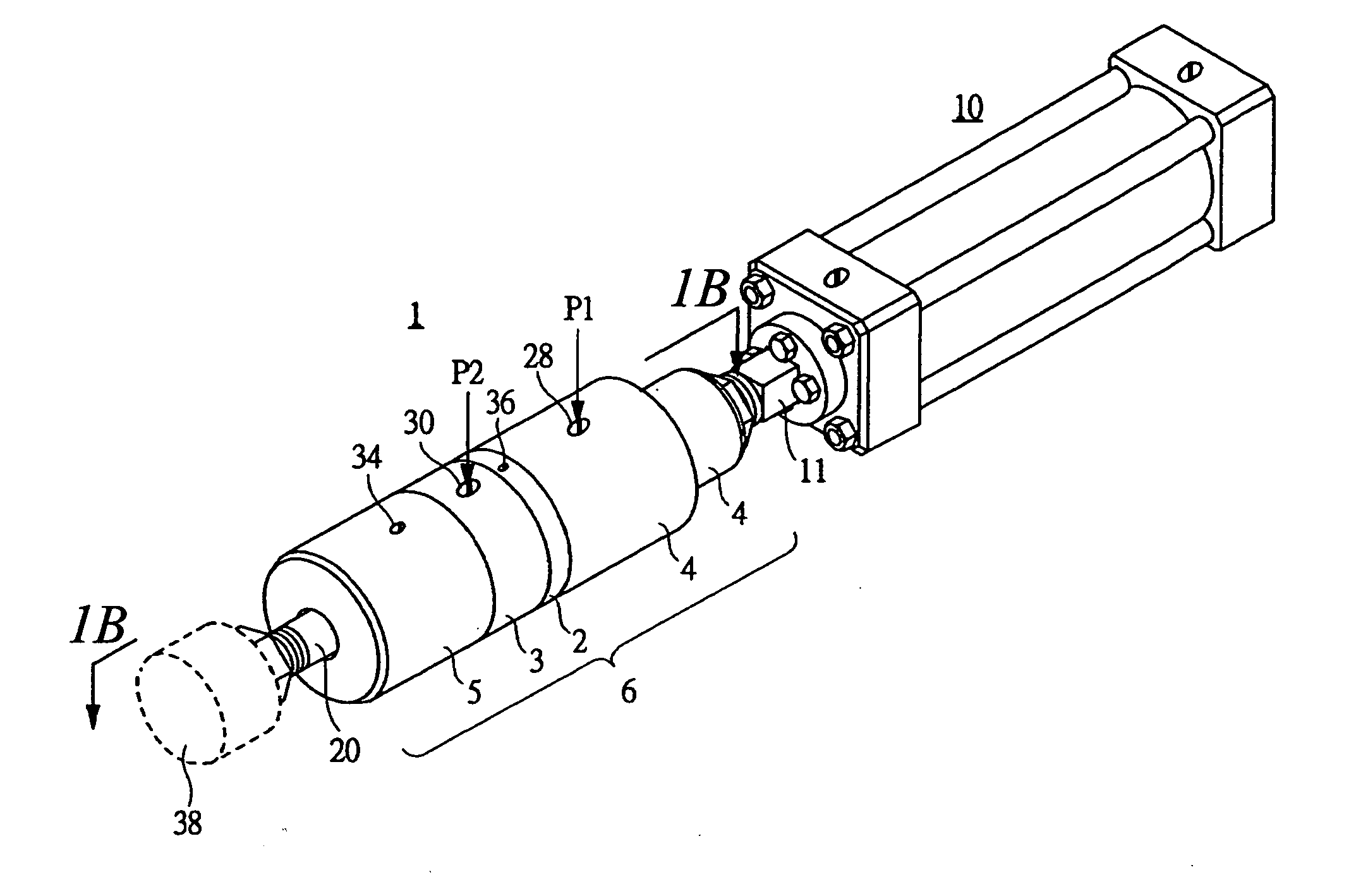
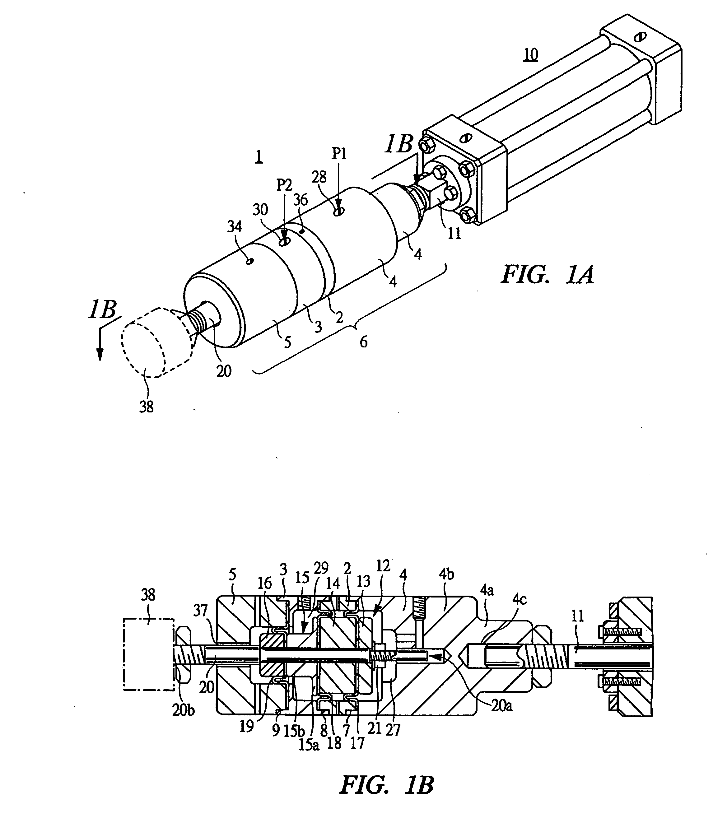
[0033]FIG. 1A is a perspective view showing a state in which a pressure device that is a first embodiment of the present invention is attached to a fluid pressure cylinder. FIG. 1B is a vertical cross-sectional view in a direction along the line a-a in FIG. 1A. In this pressure device 1, compressed air is used as working fluid, and a cylinder assembly, i.e., a cylinder body 6 is constituted by two cylinder rings 2 and 3, an end cover 4 serving as a head cover provided at one end, and an end cover 5 serving as a rod cover provided at the other end. In order to form the cylinder body 6, screw coupling portions 7 to 9 are respectively formed on outer circumferential surfaces of the cylinder rings 2 and 3 and inner circumferential surfaces of the end covers 4 and 5. Note that the cylinder rings 2 and 3 and the end covers 4 and 5 may be respectively coupled by caulking or coupled by use of sc...


PUM


Abstract

A reciprocating body 12 is reciprocably housed in a cylinder body 6, and a pressure rod 20 is reciprocably attached to this reciprocating body 12. A pressure end 20a of the pressure rod 20 protrudes from the cylinder body 12 toward the outside. By the reciprocating body 12 and diaphragms 17 to 19, an advance pressure chamber 27 and a weight offset pressure chamber 29 are partitioned and formed in the cylinder body 6. After the pressure end 20a is disposed vertically downwardly, the weight offset pressure chamber 29 is filled with compressed fluid, whereby self weight of the reciprocating body 12 and the pressure rod 20 is offset. Then, the compressed fluid is supplied to the advance pressure chamber 27, and an object to be pressurized W is pressurized through the pressure rod 20.

Description

TECHNICAL FIELD [0001] The present invention relates to a pressure device for linearly reciprocating a pressure rod by fluid pressure such as compressed air. BACKGROUND ART [0002] Devices for applying pressure to an object to be pressurized via a pressure rod include a device that carries out pressurization by converting fluid energy such as compressed air into linear motion of the pressure rod. Generally, such a pressure device is called a fluid pressure cylinder. The basic structure thereof comprises a cylinder tube in which a piston is housed to be reciprocable axially, end covers provided at both ends of the cylinder tube, and a pressure rod protruding from an end of a cylinder body formed by the cylinder tube and the end covers. The pressure rod is attached to the piston, and when fluid pressure is supplied to a pressure chamber formed in the cylinder body, the piston and the pressure rod are driven axially. [0003] Among fluid pressure cylinders, a fluid pressure cylinder of a ...

Claims


Application Information

Patent Timeline
IPC IPC(8): B41F5/00F15B11/036F15B15/10
CPCB41F15/42B41F15/423F15B11/036F15B15/10F15B2211/7055F15B2211/76
Inventor KONO, KAZUTOSHIARIIZUMI, RYOZO
Owner KOGANEI
Why Eureka
Try Eureka