Arrangement for cooling a vehicle component

a technology for vehicle components and cooling arrangements, applied in indirect heat exchangers, machines/engines, light and heating apparatus, etc., can solve the problems of affecting the lubricating properties of vehicles, affecting the cooling effect of vehicles, so as to improve the cooling capacity and reduce the temperature of the transmission

Active Publication Date: 2006-08-17
VOLVO LASTVAGNAR AB
View PDF10 Cites 8 Cited by
  • Summary
  • Abstract
  • Description
  • Claims
  • Application Information

AI Technical Summary

Benefits of technology

[0013] Preferably, according to an aspect of the invention, a cooling circuit is used, which, in turn, comprises two separate lines with two different temperatures. More precisely, these lines are in this case designed such that a lower flow is obtained in the line used to feed a coolant through th

Problems solved by technology

Not least, this requirement is great in heavy goods vehicles.
The need to cool the engine and the transmission stems from the fact that there is a risk of overheating of the engine oil and transmission oil respectively, especially under certain running conditions of the vehicle in question.
This can result, in turn, in impaired lubricating properties for the oil, which, in turn, can lead to impaired functioning and reduced working life of the engine and the transmission.
On modern engines, in which the cooling system often has a higher pressure and hence a higher temperatur

Method used


Image

  • Arrangement for cooling a vehicle component
  • Arrangement for cooling a vehicle component

Examples


Embodiment Construction

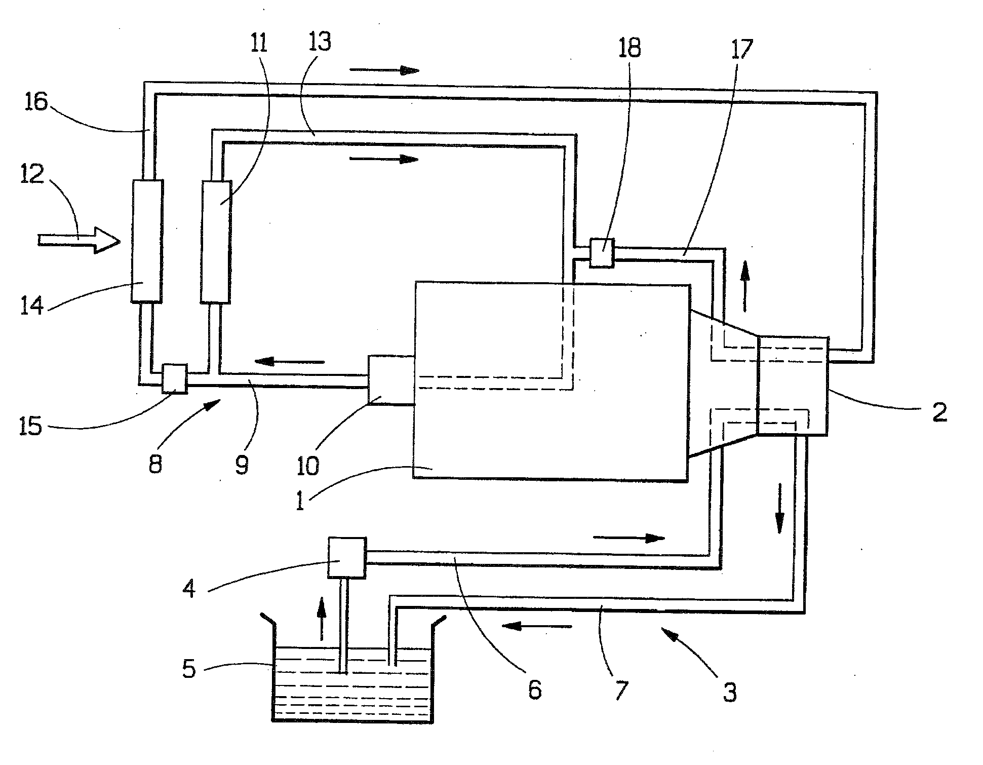
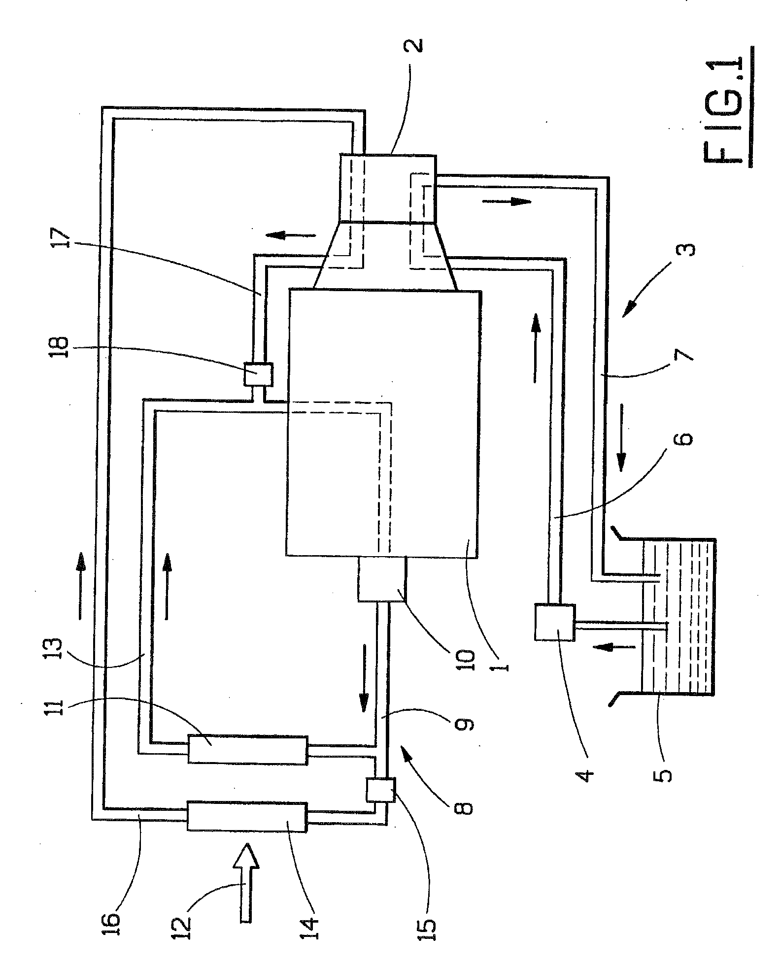
[0015] The invention will now be described below with reference to FIG. 1, which shows diagrammatically an arrangement according to a preferred embodiment of the invention. As can be seen from FIG. 1, this arrangement is based on an internal combustion engine 1 of conventional type, for example in the form of a diesel engine for a truck. A vehicle component, here in the form of a transmission 2, is arranged in a known manner adjacent to the engine 1. As stated above, for the transmission 2, there is a need for the transmission 2 to be lubricated with oil. The figure therefore basically illustrates how a lubricating oil system 3 extends through the transmission 2 for the lubrication and cooling of components forming part of the transmission 2. More precisely, for this purpose, a lubricating oil system 3 is used which has an oil pump 4 for feeding oil from an oil sump 5, via a feed line 6 and onward through the lubricating oil system 3. These components are advantageously integrated i...


PUM


Abstract

The invention constitutes an arrangement for cooling a vehicle component, for example a transmission, disposed adjacent to an engine, which arrangement includes a cooling circuit designed to feed a coolant through the transmission and including a line for coolant to the transmission and a line for coolant to the transmission. According to the invention, the cooling circuit is also designed to cool the engine and includes a further line for feeding the coolant to the engine, and the cooling circuit includes a flow control valve for controlling the coolant in the cooling circuit such that the flow of coolant to the vehicle component is lower than the flow to the engine. As a result of the invention, an improved arrangement is obtained for cooling, for example, a transmission, for example in heavy goods vehicles.

Description

[0001] The present application is a continuation of International Application No. PCT / SE2004 / 001458, filed Oct. 12, 2004, which claims priority to SE 0302740-6, filed Oct. 15, 2003, both of which are incorporated by reference.BACKGROUND AND SUMMARY [0002] The present invention relates to an arrangement for cooling a vehicle component disposed adjacent to an engine, which arrangement comprises a cooling circuit designed to feed a coolant through the vehicle component and comprising a line for coolant to the vehicle component and a line for coolant from the vehicle component. [0003] The invention is particularly intended for cooling transmissions of the type employed in motor vehicles. [0004] In connection with motor vehicles, there is a need for certain components, for example the engine and transmission of the vehicle, and other components mounted on or close to the engine, such as EGR valve (EGR=Exhaust Gas Recirculation), compressor, turbo, steering gear, etc., to be cooled. Not l...

Claims


Application Information

Patent Timeline
IPC IPC(8): F01P1/06F16H59/72F02B47/08F02B33/44F01P3/20
CPCF01P3/20F01P2050/30F01P2060/00F01P2060/045Y10T477/653F01P2060/14F16H57/0413Y10T74/19991Y10T74/2189F01P2060/12
Inventor GRUIA, MARIAN
Owner VOLVO LASTVAGNAR AB
Why Eureka
Try Eureka