
Gas distribution system

a technology of gas distribution system and distribution system, which is applied in the direction of container discharging method, special purpose vessel, packaging goods type, etc., can solve the problem that the demand at each community is too small to justify the cos

Inactive Publication Date: 2006-08-17
SINGLE BUOY MOORINGS INC
View PDF12 Cites 58 Cited by
  • Summary
  • Abstract
  • Description
  • Claims
  • Application Information

AI Technical Summary

Benefits of technology

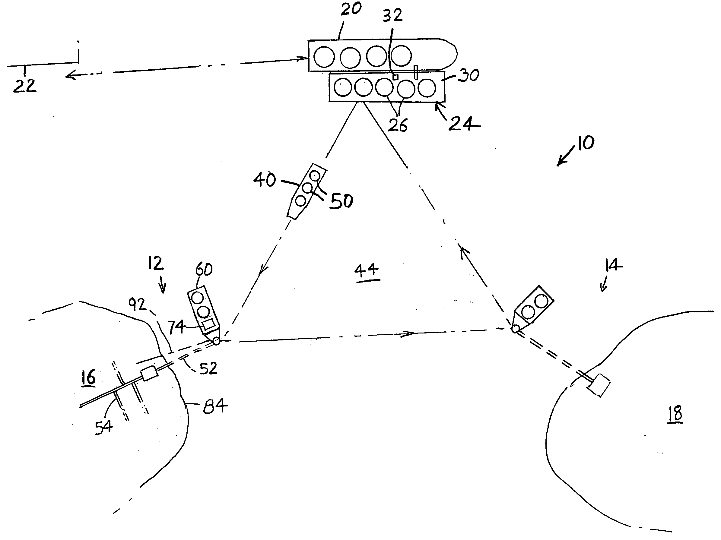
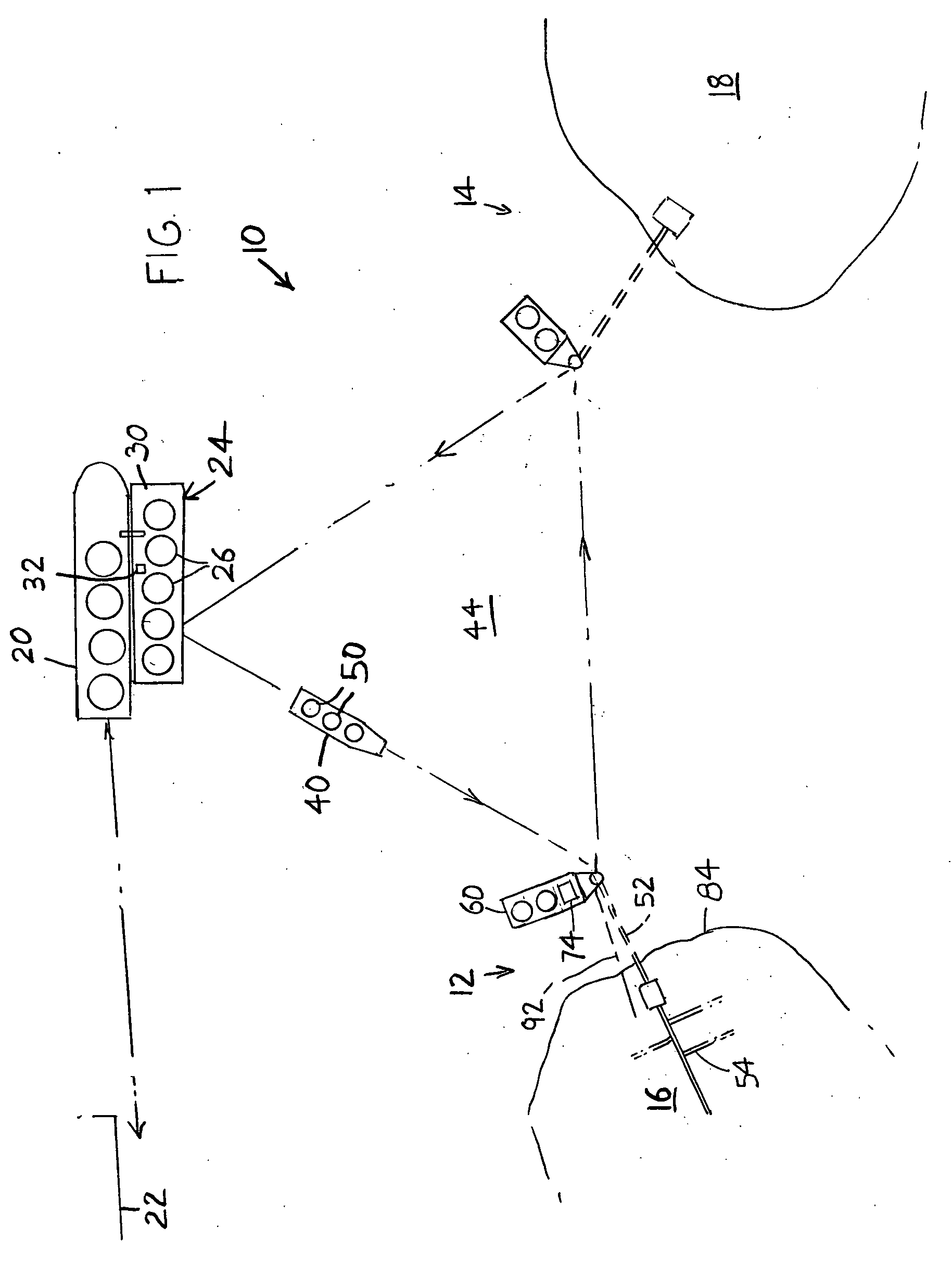
[0004] In accordance with one embodiment of the invention, an economical system is provided for distributing natural gas to each of a plurality of local coastal stations positioned in the vicinity of costal communities. The system includes a local supply station that supplies the natural gas to shuttle boats, or barges that each has a limited storage capacity. Each barge sails or is towed to one or more local coastal stations where the natural gas is unloaded to a receiving facility on a local coastal station. The local coastal station distributes the natural gas to customers lying in the vicinity of the local coastal station. Where the natural gas has been delivered as LNG (liquefied natural gas) by a tanker (storage capacity of at least

Problems solved by technology

Although gas could be supplied by LNG tankers to such isolated communities, the demand at each community is too small to justify the cost of a facility that can offload and regas (heat) the large amount of LNG carried by each tanker, and LNG suppliers generally are not interested in providing additional small tankers.

Method used


Image

  • Gas distribution system
  • Gas distribution system
  • Gas distribution system

Examples


Embodiment Construction

[0009]FIG. 1 shows a distribution system 10 for distributing natural gas (hydrocarbons that are gaseous at environmental temperatures such as 8° C. and atmospheric pressure) to each of a plurality of local coastal stations 12, 14 that lie in the vicinity of small coastal communities 16, 18 that are usually separated from each other by a plurality of kilometers. Each community generally includes less than one million people within 20 kilometers of the coastal station. The natural gas has been produced from underground (under the land and / or the sea) reservoirs that contain significant quantities of natural gas. Such reservoirs usually contain significant amounts of liquid oil (hydrocarbons that are liquid at 8° C. and atmospheric pressure) that is more easily transported to far-away customers and that is therefore more valuable to the hydrocarbon producer. Until the last few years, such produced natural gas which could not be delivered by short pipelines to local communities was ofte...


PUM

PropertyMeasurementUnit
Temperatureaaaaaaaaaa
Lengthaaaaaaaaaa
Fractionaaaaaaaaaa

Abstract

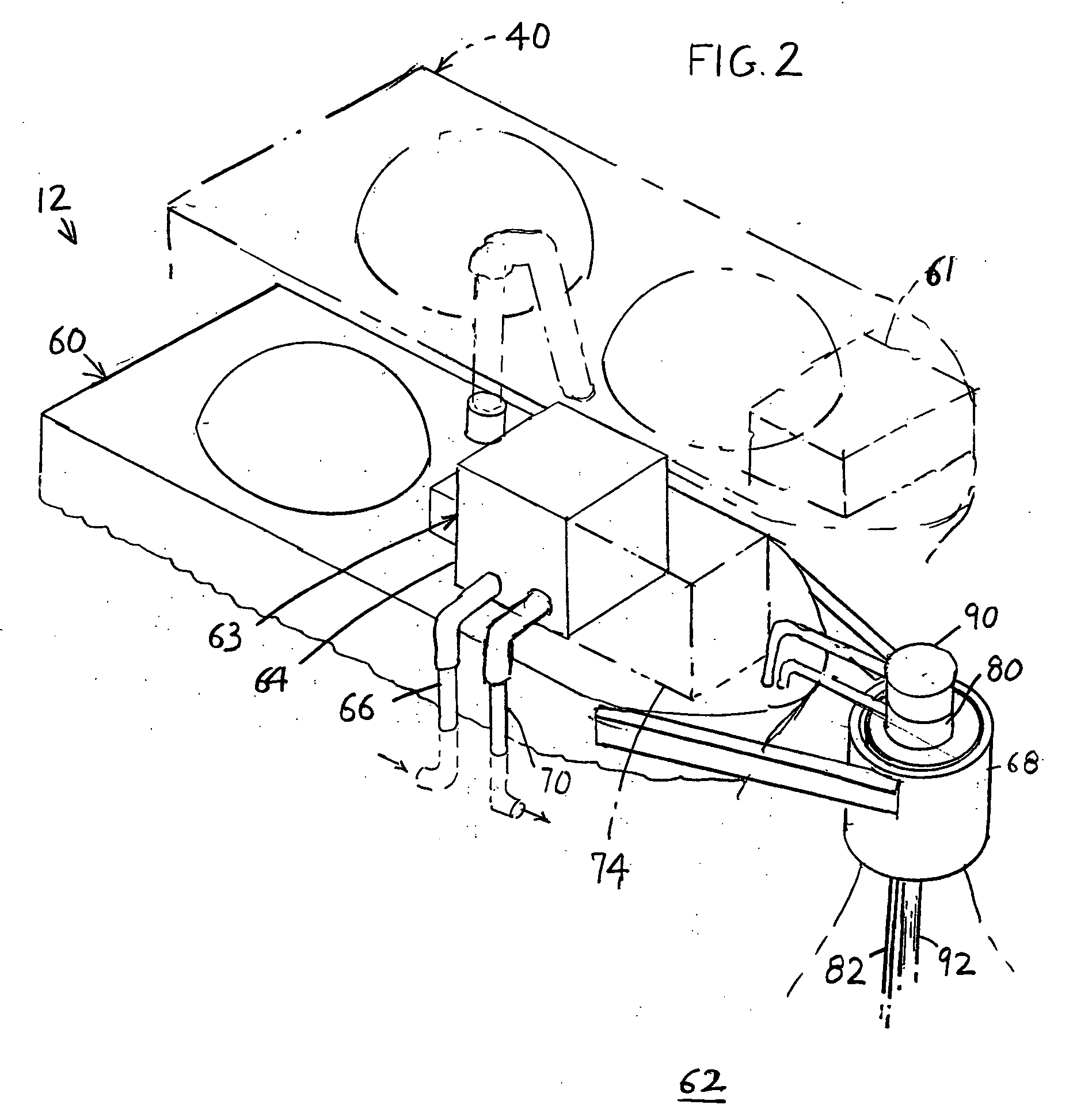
An economical system provides gaseous hydrocarbon to numerous locations (16, 18) that are each in the vicinity of an ocean coast, such as islands in a developing country, so the coastal inhabitants have access to low cost, easily supplied by pipeline and clean-burning natural gas. The system includes a local supply station (24), or hub, that stores natural gas, as by receiving LNG (liquefied natural gas) that has been liquefied by cooling it to −160° C., from a large tanker (20) having a storage capacity of over 50 million standard cubic feet of natural gas. Shuttle boats (40) that each has a much smaller LNG storage capacity than the tanker, load LNG from the local supply station, carry it to one of a plurality of local coastal stations (12, 14), heat the LNG to produce gaseous hydrocarbons, and transfer the gaseous hydrocarbons to an offshore receiving facility of the local coastal station. The gaseous hydrocarbons are then used by the local coastal station as to distribute gaseous hydrocarbons to residents of the island or to fuel an electricity generating plant.

Description

CROSS-REFERENCE [0001] Applicant claims priority from U.S. Provisional application Ser. No. 60 / 653,734 filed Feb. 17, 2005.BACKGROUND OF THE INVENTION [0002] Natural gas is the most common type of hydrocarbon that is in a gaseous state at common environmental temperatures (e.g. 8° C.). Natural gas is well recognized as a low cost, easily-handled and clean burning fuel, as it is often priced below liquid oil, it can be distributed to households and businesses by pipeline, and it creates little emissions other than carbon dioxide. Natural gas is produced at many locations in much larger quantities than can be used locally, and it is transported to faraway customers by cooling it as to −160° C. to produce LNG (liquefied natural gas). The LNG is transported in tankers that each has a capacity of more than 50 million standard (atmospheric pressure and environmental temperature) cubic feet of natural gas, to far away receiving locations. The receiving locations are usually large facilitie...

Claims


Application Information

Patent Timeline
IPC IPC(8): B67C3/02B65B1/04B65B3/04
CPCB63B22/026F17C7/02F17C2265/05F17C2201/052F17C2221/033F17C2223/0123F17C2223/0161F17C2223/033F17C2223/036F17C2225/0123F17C2225/036F17C2227/0311F17C2227/0318F17C2265/061F17C2270/0105F17C2270/0113F17C2270/0123F17C2270/0163Y10T137/0318Y10T137/402
Inventor HARLAND, LEON ANDRESIDDIQUI, MOHSINVAN WIJNGAARDEN, WILLEM CORNELIS
Owner SINGLE BUOY MOORINGS INC
Learn More