Power control unit

a power control unit and power control technology, applied in the direction of machine/engine, propulsion using engine-driven generators, process and machine control, etc., can solve the problems of difficulty in achieving the acceleration speed the rider desires, troublesome control sequence, and complicated structur

Inactive Publication Date: 2006-08-17
HONDA MOTOR CO LTD
View PDF6 Cites 216 Cited by
  • Summary
  • Abstract
  • Description
  • Claims
  • Application Information

AI Technical Summary

Benefits of technology

[0018] The present invention has been made in view of the above problems and has an object to provide a power control unit which eliminates the need for control mode selection and provides an adequate acceleration speed in response to the rider's accelerator operation.
[0019] The present invention has an object to provide a power control unit by which the driving mode is changed over through a simple structure and a simple control sequence and engagement noise generation accompanied by driving mode switching is suppressed.
[0020] An object of the present invention is to provide a power control unit which has a simple structure to eliminate slip in a hybrid vehicle in which power of the engine and power of the drive motor are transmitted to a driving wheel through the same drive shaft.

Problems solved by technology

However, in the device as described in JP-A No. 58295 / 1997, even if only the operation speed is increased, the driving feeling does not change and the acceleration speed which the rider desires cannot be obtained.
When the driving mode is switched from the motor driving mode to the engine driving mode, if the driving force and rotation speed of the motor do not agree with those of the engine, some engagement noise may be generated by engagement of the clutch.
In the hybrid vehicle described in JP-A No. 23312 / 2000, the torque and rotation speed of the engine and motor are controlled, which requires a complicated structure and a troublesome control sequence.
Particularly, a torque sensor is generally expensive and complicated.
Besides, there is concern that response to driving mode switching may deteriorate as the structure is complicated.
Particularly in vehicles which adopt the series hybrid system, it may be difficult to eliminate slip by changeover from a two-wheel drive mode to a four-wheel drive mode as described in the above JP-A No. 63392 / 2001 because they often use a mechanism that transmits power of the engine and power of the drive motor to a driving wheel through the same drive shaft.
Furthermore, in the traction control disclosed in JP-A No. 35329 / 1998, in order to stop fuel supply to the engine, a fuel shutoff valve must be provided separately and the system cannot be used when the vehicle is driven by the motor, so another system must be provided for a situation that it is driven by the motor.
Similarly, the traction control disclosed in JP-A No. 232697 / 1996 cannot be used when the vehicle is driven by the motor and another system must be provided for a situation that the vehicle is driven by the motor.

Method used


Image

  • Power control unit
  • Power control unit
  • Power control unit

Examples


Embodiment Construction

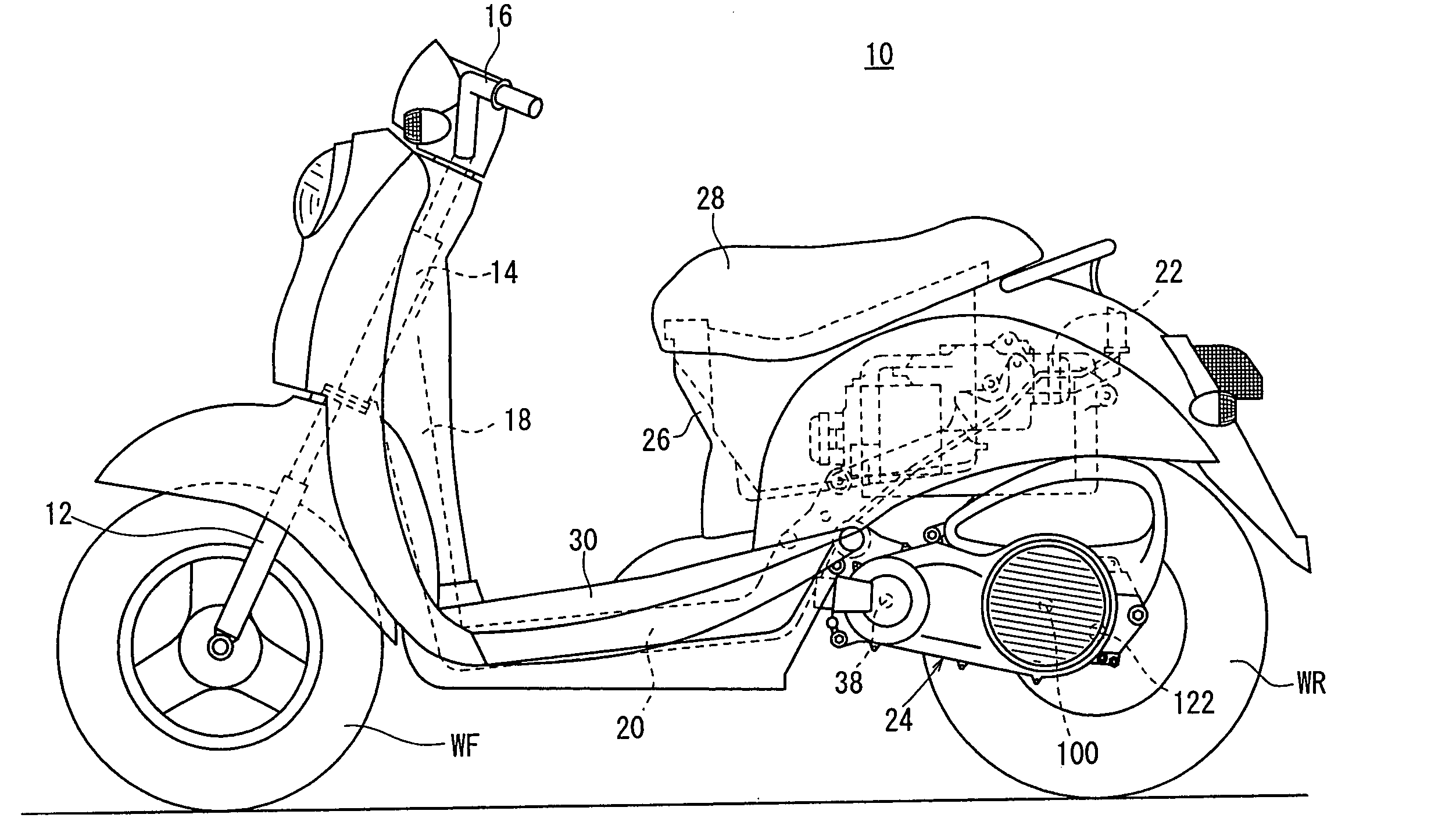
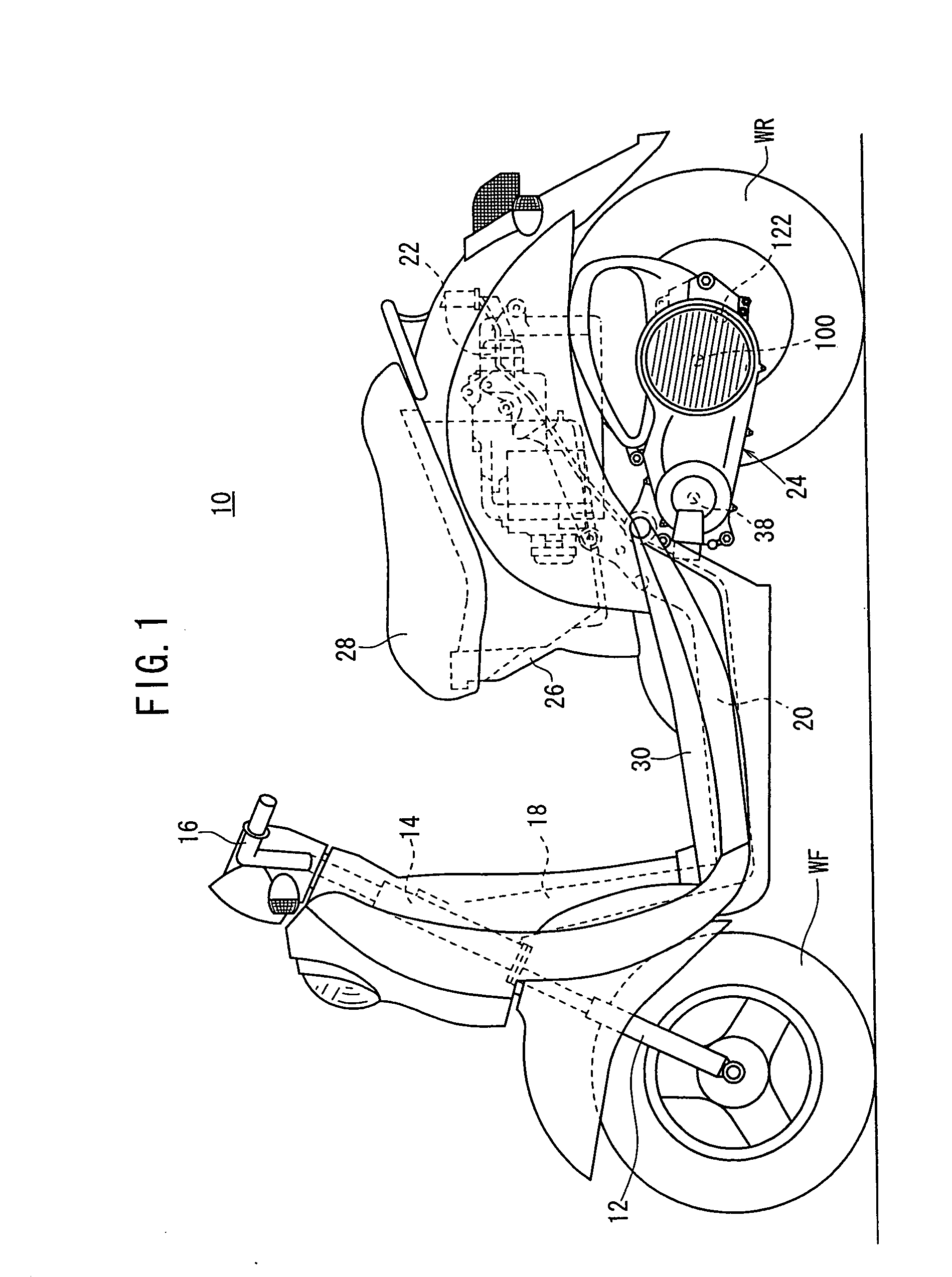
[0086] Next, a power control unit according to the present invention as an embodiment thereof will be described referring to the accompanying drawings FIGS. 1 to 24B. First, a hybrid vehicle 10 on which a power control unit 150 (see FIG. 5) according to this embodiment is mounted will be described referring to FIGS. 1 to 3.

[0087] The hybrid vehicle 10 is a scooter type motorcycle and has front forks 12 axially supporting a front wheel WF on the vehicle body front side and the front forks 12 are steered by means of a handlebar 16 through a head pipe 14. The right grip of the handlebar 16 can be rotated and functions as an accelerator. An amount of accelerator operation Acc (see FIG. 5) is detected by an accelerator sensor 152 (see FIG. 5).

[0088] A down pipe 18 is fitted backward and downward to the head pipe 14 and a middle frame 20 extends almost horizontally from the lower end of the down pipe 18. A rear frame 22 is fitted to the rear end of the middle frame 20 backward and upwar...


PUM


Abstract

A hybrid vehicle includes an engine and a drive motor which adds power to power generated by the engine in a superimposed manner to assist the engine. A power control unit includes: a fourth rotor sensor as a vehicle speed sensor which detects vehicle speed of the hybrid vehicle; an accelerator sensor which detects an amount of accelerator operation; and an ECU having an assist map which determines an output command reference value for the drive motor based on the vehicle speed and the amount of accelerator operation. The ECU outputs, to the drive motor, a corrected output command value which is calculated by adding an additional value corresponding to a rate of change in the amount of accelerator operation, to the output command reference value obtained from the assist map.

Description

BACKGROUND OF THE INVENTION [0001] 1. Field of the Invention [0002] The present invention relates to a power control unit in a hybrid vehicle having an engine which generates power to be transmitted to a driving wheel and a motor which adds power to the power generated by the engine in a superimposed manner to assist the engine. [0003] 2. Description of the Related Art [0004] In recent years, hybrid vehicles which combine an internal combustion engine and an electric motor to generate power and transmit it to driving wheels have been developed and commercialized for reduction in fuel consumption and gas emissions. [0005] In a hybrid vehicle, since the generated torque can be varied easily by controlling electric power to the motor, a device which uses this feature to give a rider a driving feeling which he / she desires has been proposed in JP-A No. 58295 / 1997 (Japanese Laid-Open Patent Publication No. 9-58295). In this device, three control modes are available where different torque ...

Claims


Application Information

Patent Timeline
Patent Type & Authority Applications(United States)
IPC IPC(8): B60K6/00B60L50/10B60K6/26B60K6/383B60K6/48B60K6/543B60L50/16B60W10/02B60W10/04B60W10/06B60W10/08B62K11/00F02D29/02
CPCB60K6/48Y02T10/70B60L2200/12B60W10/06B60W10/08B60W20/00B60Y2200/12B62K2202/00B62K2204/00B62M7/12Y02T10/6221Y02T10/6286Y02T10/7077Y02T10/7258B60L11/14B60L50/16Y02T10/62Y02T10/72Y02T10/7072A01G13/0293B60W20/10
Inventor UCHISASAI, HIROAKIKOJIMA, HIROYUKITSUKADA, YOSHIAKIOZEKI, TAKASHI
Owner HONDA MOTOR CO LTD
Why Eureka
Try Eureka