Smart thermal imaging and inspection device for wheels and components thereof and method

Inactive Publication Date: 2006-08-17
SPIRIT SOLUTIONS
View PDF28 Cites 33 Cited by
  • Summary
  • Abstract
  • Description
  • Claims
  • Application Information

AI Technical Summary

Benefits of technology

[0019] There has thus been outlined, rather broadly, the more important features of the invention in order that the detailed description thereof may be better understood, and in order that the present contribution to the art may be better appreciated. There are additional features of the invention that will be described hereinafter. In this respect, before explaining at least one embodiment of the invention in detail, it is to be understood that th

Problems solved by technology

The detection of the hottest point of an axle or a bearing can obscured or difficult to read in some instances.
However, the integration that is provided by the detection of a relatively wide area in the longitudinal direction of the axles leads overall to a relatively small difference of the signals that are measured, so that reliable analysis is not possible without some difficulty.
One problem with the conventional Hotbox is that it employs a single pyrometer to determine temperature.
Another problem with conventional Hotbox technology is the viewing window can easily become blocked due to leaves and other objects blocking the view due in part to the fact the Hotbox faces towards the sky.
Another problem with conventional Hotbox technology is that weather conditions can block the field of view.
The fundamental problem

Method used


Image

  • Smart thermal imaging and inspection device for wheels and components thereof and method
  • Smart thermal imaging and inspection device for wheels and components thereof and method
  • Smart thermal imaging and inspection device for wheels and components thereof and method

Examples


Embodiment Construction

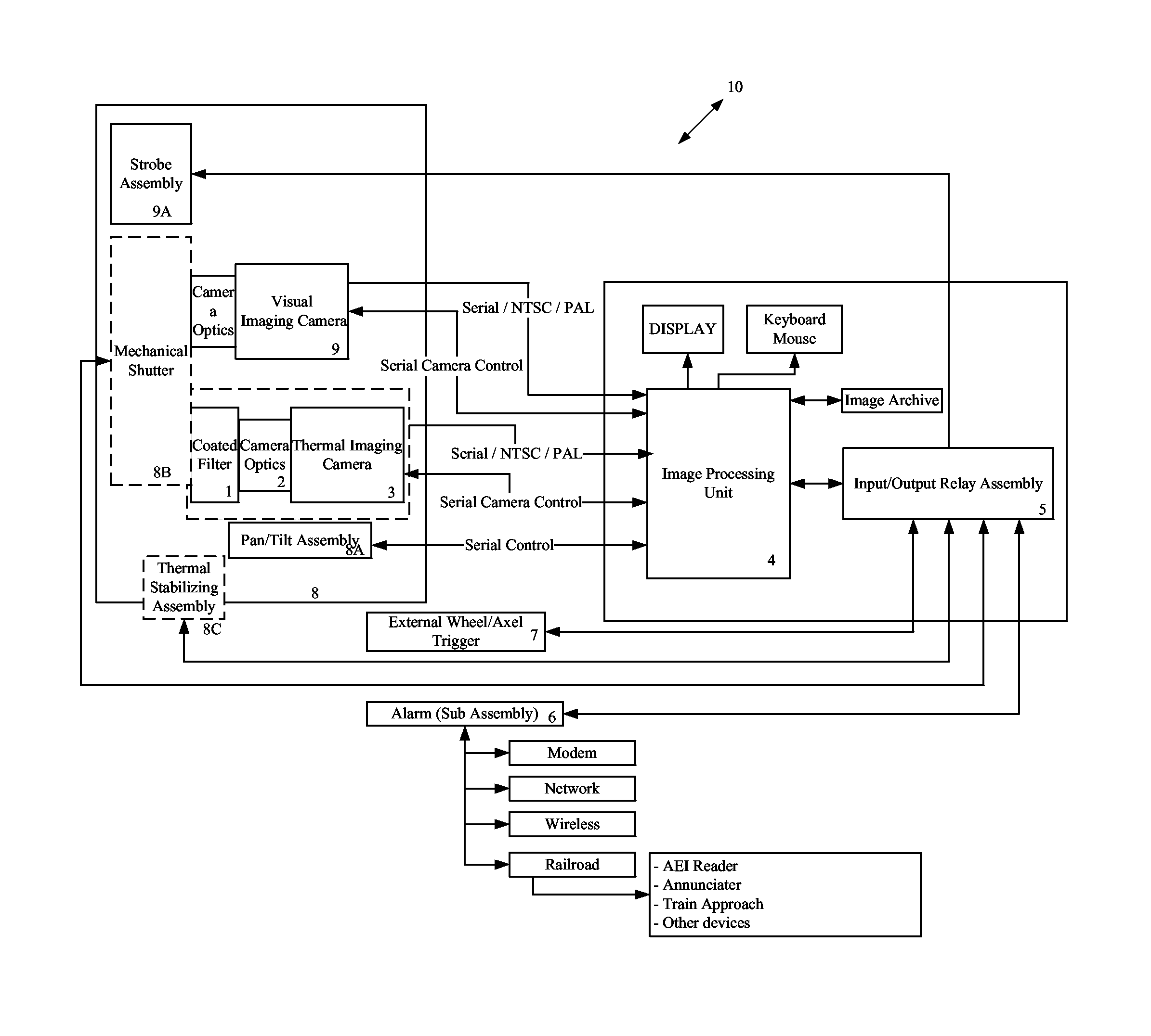
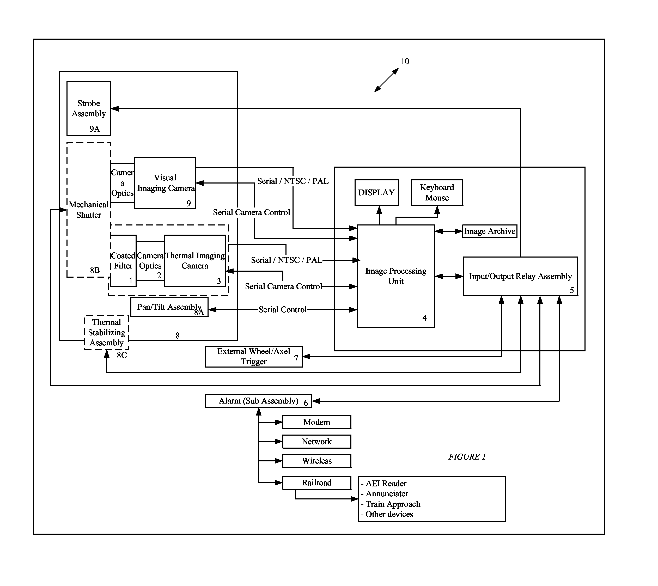
[0025] Turning now to the drawings, in which similar reference characters denote similar elements throughout the several views, the attached illustrations show a smart thermal imaging and inspection (hereinafter referred to as “STII”) device for wheels and components thereof which is generally designated by the numeral 10. The STII device 10 includes a thermal imaging camera 3, and imaging processing unit 4 and input / output relay assembly 5.

[0026] The thermal imaging camera 3 is comprised of a 2D focal plane array, camera optics 2, and coated filter 1, wherein the thermal imaging camera 3 is sensitive in the 8 to 14 micron range. The STII device 10 can utilize either an electronic or a spectral optical coated band pass filter to focus on specific wavelengths, such as molten steel that is in the region of 2 to 3 microns to generate thermal data to be normalized and / or analyzed. By employing the thermal imaging camera 3 and associated camera optics 2 and coated filter 1, a range of 1...


PUM


Abstract

A smart thermal imaging and inspection of wheels for the automatic inspection and analysis of railroad car wheels but can also be used for wheeled object that contain a bearing. The inventive device includes a thermal imaging camera, visual imaging camera, imaging processing unit. Users interface which allows for all parameters to be set.

Description

[0001] This application claims the benefit of provisional application U.S. 60 / 653,850 filed Feb. 14, 2005.BACKGROUND OF THE INVENTION [0002] 1. Field of the Invention [0003] The present invention relates generally to railroad Hotboxes and more specifically it relates to a smart thermal imaging and inspection device for wheels and components thereof for the automatic inspection and analysis of railroad car wheels or other wheeled vehicles. [0004] 2. Description of the Related Art [0005] It can be appreciated that various forms of thermal imaging have been in use for years reading the temperature of wheels. A technology termed the Hotbox is the most common device and is found on railroads and uses infrared temperature measurements. [0006] One type of system for measuring impermissible temperature increases of railway rolling stock wheels that are running hot includes an infrared temperature receiver which is usually located close to the rails so that an active window that subtends an ...

Claims


Application Information

Patent Timeline
IPC IPC(8): G01J5/02
CPCG01J5/0022G01J5/02G01J5/025G01J5/026G01J5/08G01J5/0846G01J2005/0048G01J2005/0077G01N25/72G01J5/80
Inventor LANE, T RANDALLSCHLAGHECK, JERRY
Owner SPIRIT SOLUTIONS
Why Eureka
Try Eureka